background image

Troubleshooting

The front of the RPS provides a quick reference troubleshooting guide. For
more details use the following table to diagnose your RPS.

LED

State

Meaning of LED

AC Power

(green)

On

Off

Flash

The RPS is receiving power.

The RPS is not receiving power on both AC inputs.

The RPS is not receiving power from one of the AC inputs. Verify that both of the AC
power cords are plugged into an operating AC power source.

DC Power Out

(green)

On

Off

Flash

A device is connected to the DC Power Out connector and is receiving redundant power.

A device is not connected to one of the DC Output connectors. Verify the device is
connected properly. If the connector appears snug on both ends, try using a different DC
power cord.

A device is connected to the RPS but one of the DC to DC converters has failed. The
other DC to DC is still providing power. Call your HP Authorized Dealer or the nearest
HP Sales and Support office.

Overtemp
(orange

)

Off

Flash

The RPS is running at a normal temperature.

The RPS has reached 70°C or higher, and needs more adequate ventilation.

Fan
(green)

On

Flash

The fans are on and operating normally.

One or both of the fans has malfunctioned.

Fault
(orange)

Off

Flash

No faults have been detected on the RPS.

A failure has been detected. The corresponding LED will also flash.

Troubleshooting

12

Summary of Contents for J2962A

Page 1: ......

Page 2: ......

Page 3: ...name of the file For example asfw exe x HP FTP Library Service 1 FTP to Internet IP Address ftp ftp boi external hp com 2 Log in as anonymous and press Return at the password prompt 3 Type bin to set the file type 4 Type cd pub networking software 5 Type get filename e g icmupdt exe to transfer the file to your computer 6 Quit the FTP session CompuServe 1 Login to CompuServe 2 Type go hpsys 3 Type...

Page 4: ......

Page 5: ...HP AdvanceStack Redundant Power Supply Installation and Reference Guide ...

Page 6: ... for incidental or consequential damages in connection with the furnishing performance or use of this material Hewlett Packard assumes no responsibility for the use or reliability of its software on equipment that is not furnished by Hewlett Packard Warranty A copy of the specific warranty terms applicable to your Hewlett Packard product and replacement parts can be obtained from your HP Sales and...

Page 7: ...e RPS 3 Installation Summary 4 Included Parts 4 1 Mount the RPS 5 2 Connect the RPS to Supported Devices 8 3 Verify the RPS s Operation 9 How the RPS Works 10 Frequently Asked Questions 11 Troubleshooting 12 Specifications 16 Safety Information 18 Index 27 Table of Contents ...

Page 8: ...y and diagnostic information about the RPS Also each supported device has an RPS LED to report the status of the Redundant Power Supply Handy troubleshooting key located on the front of the RPS to quickly diagnose the meaning of the LEDs RPS status information available from HP Stack Manager Windows 3 1 software shipped with the devices that support the RPS and HP Interconnect Manager Management S...

Page 9: ...RPS status LEDs Front of the RPS LED Troubleshooting Key DC power receptacles for four devices Two AC power receptacles Back of the RPS HP Redundant Power Supply 3 ...

Page 10: ...t HP Redundant Power Supply Installation and Reference Guide this manual J2962 90001 Two AC power cords one of the following Australia New Zealand Denmark Europe Japan Switzerland United Kingdom U S Canada Mexico Taiwan 8120 6175 8120 6178 8120 6174 8120 5342 8120 6179 8120 6173 8120 6776 Four 34 inch 86 4 cm DC power cords 8120 6777 to connect the supported HP devices Accessory kit 5063 8522 two ...

Page 11: ...ion To determine the possibility of over loading the supply circuits add together the ampere ratings from the nameplates of the RPS and other equipment installed on the same cir cuits and compare the total with the rating limits for the supply circuits Make sure that the power source circuits are properly grounded then use the supplied power cord to connect the RPS to the circuit See the Safety St...

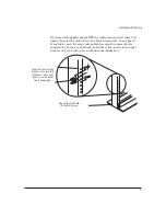
Page 12: ...he RPS with the 10 mm M4 screws included in the accessory kit 5063 8522 The top of each bracket should align with the top of the RPS Be careful not to overtighten the screws 2 Partially install a screw 5 8 inch number 12 24 included in the accessory kit in each rack upright Ensure that the screws in each upright are at the same level align top of bracket with top of RPS 10 mm M4 screws Installatio...

Page 13: ...rack the screw hole pattern has repetitive pairs of holes separated by 0 5 inch or 0 625 inch Insert these first screws in the upper hole of a close 0 5 inch pair as shown in the illustration Insert a screw into the top hole of a close 0 5 inch pair like one of these one in each of the rack uprights One upright of an EIA 19 inch telco rack Installation Summary 7 ...

Page 14: ...0Base T Hub 48 2 Notify the users on these devices that the network will be down temporarily 3 Disconnect the AC power cord from the selected device and store the AC power cord 4 Connect a DC cable 8120 6777 to the RPS and to the RPS connector on the selected device The following illustration shows the HP Hub 48 connected to the RPS RPS RPS AC power cords connected to an operating AC power source ...

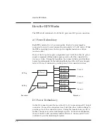
Page 15: ... power cords from the RPS AC Power connector to a reliable AC power source HP recommends two separate AC power lines for added redundancy 2 Check the LEDs on the RPS s front panel During Power On All LEDs are on for one second After Power On AC Power LEDs are on Connected DC Power Output LEDs are on Fan is on If the Fault LED is on see the troubleshooting table on page 12 Hub 24 Hub 24 Hub 48 Hub ...

Page 16: ...or interrupted In the following illustration if the AC Power 1 supply fails AC Power 2 continues to provide power to the connected devices DC Power Redundancy On the DC connector side there are two DC to DC converters per DC Output connector If one of the converters were to fail the other would continue to provide power to the connected device During the transfer from one DC to another the device ...

Page 17: ... Should I keep my device s AC power cord connected No This configuration is not supported by HP I have only one device connected to the RPS What would happen if I connected only one AC power cord to the RPS You will have redundant DC power but not redundant AC power If I connect a DC cable to DC Power Output 1 and an AC power cord to AC Power 2 will the device receive power Yes However you should ...

Page 18: ...ot connected to one of the DC Output connectors Verify the device is connected properly If the connector appears snug on both ends try using a different DC power cord A device is connected to the RPS but one of the DC to DC converters has failed The other DC to DC is still providing power Call your HP Authorized Dealer or the nearest HP Sales and Support office Overtemp orange Off Flash The RPS is...

Page 19: ...b CompuServe and the HP FTP Library Service After you download the file s from one of these sources you type filename x For example icmupdt exe x HP BBS and World Wide Web The HP BBS phone number is 208 344 1691 Set your modem communication settings to parity N data bits 8 stop bits 1 baud rates 300 1200 2400 4800 9600 or 14400 The URL address for the World Wide Web is http www hp com go network_c...

Page 20: ...e ftp prompt appears 2 At the ftp prompt enter anonymous 3 At the password prompt enter your internet e mail address 4 At the ftp prompt set the file type to binary binary 5 Retrieve the file by entering get filename exe For example icmupdt exe 6 Quit the FTP session by entering quit 7 Extract the file e g icmupdt x Troubleshooting 14 ...

Page 21: ... service that is available 24 hours a day seven days a week HP FIRST provides information on product informa tion troubleshooting technical reviews and configuration information To access HP FIRST dial one of the following phone numbers from your touch tone telephone Location Phone Number U S and Canada Only 800 333 1917 and press 1 for HP FIRST Outside the U S and Canada 208 344 4809 and press 9 ...

Page 22: ... Hz DC voltage 65 watts per DC connector 5 volts 12 volts 12 volts 9 4 A at 5 volts 1 0 A at 12 volts 0 5 A at 12 volts Environmental Operating Non Operating Temperature 0 C to 55 C 32 F to 131 F 40 C to 70 C 40 F to 158 F Relative humidity non condensing 15 to 95 at 40 C 104 F 90 at 65 C 149 F Maximum altitude 4 6 km 15 000 ft 4 6 km 15 000 ft Safety IEC 950 1991 A1 A2 EN60950 I 1992 A1 A2 UL1950...

Page 23: ...5 Class A EN 55022 CISPR 22 Class A VCCI Level I Immunity See the Declaration of Conformity for details at the end of the Regulatory Statements Complies with Canadian EMC Class A requirements Acoustic Noise 5 5 Bels max Specifications 17 ...

Page 24: ...he product s input wiring terminals power cord or supplied power cord set Whenever it is likely that the protection has been impaired disconnect the power cord until the ground has been restored For LAN cable grounding If your LAN covers an area served by more than one power distribution system be sure their safety grounds are securely interconnected LAN cables may occasionally be subject to hazar...

Page 25: ...entation ou le cordon de raccordement fourni avec le produit Lorsque cette protection semble avoir été endommagée débrancher le cordon d alimentation jusqu à ce que la mise à la terre ait été réparée Mise à la terre du câble de réseau local si votre réseau local s étend sur une zone desservie par plus d un système de distribution de puissance assurez vous que les prises de terre de sécurité soient...

Page 26: ...erminals den Netzkabeln oder dem mit Strom belieferten Netzkabelsatz voraus Sobald Grund zur Annahme besteht daß der Schutz beeinträchtigt worden ist das Netzkabel aus der Wandsteckdose herausziehen bis die Erdung wiederhergestellt ist Für LAN Kabelerdung Wenn Ihr LAN ein Gebiet umfaßt das von mehr als einem Stromverteilungssystem beliefert wird müssen Sie sich vergewissern daß die Sicherheitserdu...

Page 27: ... oppure al set cavo d alimentazione fornito con il prodotto Ogniqualvolta vi sia probabilità di danneggiamento della protezione disinserite il cavo d alimentazione fino a quando il collegamento a terra non sia stato ripristinato Per la messa a terra dei cavi LAN se la vostra LAN copre un area servita da più di un sistema di distribuzione elettrica accertatevi che i collegamenti a terra di sicurezz...

Page 28: ...to el cable de alimentación o el juego de cable de alimentación suministrado Si existe la probabilidad de que la protección a tierra haya sufrido desperfectos desenchufar el cable de alimentación hasta haberse subsanado el problema Puesta a tierra del cable de la red local LAN Si la LAN abarca un área cuyo suministro eléctrico proviene de más de una red de distribución de electricidad cerciorarse ...

Page 29: ...Safety Information Safety Information 23 ...

Page 30: ... equipment in a residential area is likely to cause interference in which case the user at his own expense will be required to take whatever measures may be required to correct the interference If this equipment causes interference to radio reception which can be determined by unplug ging the power cord from the equipment try these measures Re orient the receiving antenna Relocate the equipment wi...

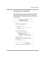
Page 31: ... the HP AdvanceStack Redundant Power Supply complies with ISO IEC Guide 22 and EN 45014 The declaration identifies the product the manufacturer s name and address and the applicable specifications that are recognized in the European community Declaration of Conformity 25 ...

Page 32: ...26 ...

Page 33: ...of 10 Declaration of Conformity 25 E electrical specifications 16 electromagnetic specifications 17 environmental specifications 16 F Fan LED 12 FAQ frequently asked questions 11 Fault LED 12 fax using to get HP product information 15 frequently asked questions 11 ftp obtaining files from HP 14 H Hourly support calling for 15 HP FIRST Fax Retrieval Service using 15 HP FTP Library Service using 14 ...

Page 34: ...ifications 16 R rack mounting 6 Regulatory statements 24 RPS connecting to supported devices 8 verifying operation of 9 S Safety information 18 self test LED state 9 software updates downloading electronically 13 specifications electrical 16 electromagnetic 17 environmental 16 physical 16 supported devices 8 T table mounting 5 troubleshooting 12 15 W World Wide Web obtaining software from 13 WWW o...

Page 35: ......

Page 36: ...Copyright 1995 1998 Hewlett Packard Company Printed in Singapore 04 98 Manual Part Number J2962 90001 J2962 90001 ...

Reviews: