Chapter 1
27
Product Information
Internal Components
Internal Components
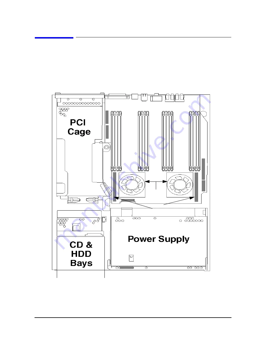
This section describes the internal components of the J6700 workstations.
For instructions on how to remove the workstation’s top panel in order to access these
internal components, as well as instructions on how to remove and replace these internal
components to service them, see Chapter 4.
Figure 1-7. Internal Components of the J6700
System Board
The system board in the J6700 contains the PA-RISC microprocessors, memory slots, and
PCI cage as well as connectors to other components.
Memory Slots
16
VRMs
Processor 0
Processor 1
Summary of Contents for j6700
Page 1: ...Service Handbook HP VISUALIZE J6700 Workstations Manufacturing Part Number n a Edition E0501 ...
Page 8: ...8 Contents ...
Page 30: ...30 Chapter1 Product Information Monitors ...
Page 76: ...76 Chapter3 Troubleshooting Using the System Board LEDs for Troubleshooting ...
Page 100: ...100 Chapter4 Field Replaceable Units FRUs FRU Removal and Replacement ...
Page 134: ...134 Chapter5 Boot Console Handler Initial System Loader ISL Environment ...
Page 150: ...150 Appendix B SCSI Connections How To Connect An SE SCSI Device ...


