background image

4

HP 10.9/13.5 dBi Dual-Band Point-to-Point 3-Element MIMO Directional Antenna (J9170A) Guide

0

350

340

330

320

310

300

290

280

270

260

250

240

230

220

210

200

190

180

170

160

150

140

130

120

110

100

90

80

70

60

50

40

30

20

10

-20

-10

0

dB

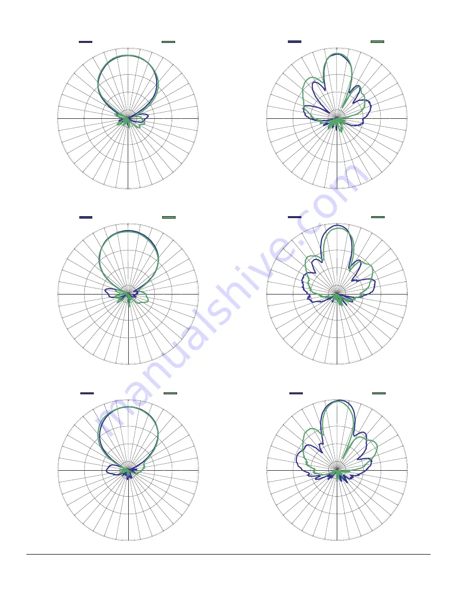
H Plane

2.45 GHz (Port 2 Vertical Polarization)

E Plane

0

350

340

330

320

310

300

290

280

270

260

250

240

230

220

210

200

190

180

170

160

150

140

130

120

110

100

90

80

70

60

50

40

30

20

10

-20

-10

0

dB

H Plane

2.45 GHz (Port 1 Vertical Polarization)

E Plane

0

350

340

330

320

310

300

290

280

270

260

250

240

230

220

210

200

190

180

170

160

150

140

130

120

110

100

90

80

70

60

50

40

30

20

10

-20

-10

0

dB

H Plane

2.45 GHz (Port 3 Horizontal Polarization)

E Plane

0

350

340

330

320

310

300

290

280

270

260

250

240

230

220

210

200

190

180

170

160

150

140

130

120

110

100

90

80

70

60

50

40

30

20

10

-20

-10

0

dB

H Plane

5.47 GHz (Port 1 Vertical Polarization)

E Plane

0

350

340

330

320

310

300

290

280

270

260

250

240

230

220

210

200

190

180

170

160

150

140

130

120

110

100

90

80

70

60

50

40

30

20

10

-20

-10

0

dB

H Plane

5.47 GHz (Port 2 Vertical Polarization)

E Plane

0

350

340

330

320

310

300

290

280

270

260

250

240

230

220

210

200

190

180

170

160

150

140

130

120

110

100

90

80

70

60

50

40

30

20

10

-20

-10

0

dB

H Plane

5.47 GHz (Port 3 Horizontal Polarization)

E Plane

Summary of Contents for J9170A

Page 1: ...ntact electrical lines 5998 0860 HP 10 9 13 5 dBi Dual Band Point to Point 3 Element MIMO Directional Antenna J9170A Guide SAFETY The HP J9170A antenna and all associated equipment should be installed in accordance with applicable local and national electrical code guidelines to ensure safe operation Before connecting an outdoor antenna to an HP Wireless Access Point be sure that the access point ...

Page 2: ...ng see wall diagram figure 3 for holes size b Install 4 wall expansion anchors 12 c Install to wall the antenna mount bracket using four SS HEX 1 4 20 screws 13 4 SS 1 4 20 flat washers 8 4 1 4 20 lock washer 9 Or for mounting on a pole or mast attach the two hose clamps 11 to antenna mount bracket 1 and encircle the pole with each clamp and tighten 4 Attach the pre assembled antenna with both 1 a...

Page 3: ...tall a lightning arrester HP J8996A or equivalent for each port of the antenna Lightning arresters must be purchased separately For best results install the lightning arrester in close proximity to a low resistance ground at a point where the coaxial cable enters the building or attaches to an AP For exterior installations use weatherproof coaxial connectors with a suitable mastic or rubberized ta...

Page 4: ... 220 210 200 190 180 170 160 150 140 130 120 110 100 90 80 70 60 50 40 30 20 10 20 10 0 dB H Plane 2 45 GHz Port 3 Horizontal Polarization E Plane 0 350 340 330 320 310 300 290 280 270 260 250 240 230 220 210 200 190 180 170 160 150 140 130 120 110 100 90 80 70 60 50 40 30 20 10 20 10 0 dB H Plane 5 47 GHz Port 1 Vertical Polarization E Plane 0 350 340 330 320 310 300 290 280 270 260 250 240 230 2...

Page 5: ...5 725 GHz Port 1 Vertical Polarization E Plane 0 350 340 330 320 310 300 290 280 270 260 250 240 230 220 210 200 190 180 170 160 150 140 130 120 110 100 90 80 70 60 50 40 30 20 10 20 10 0 dB H Plane 5 725 GHz Port 2 Vertical Polarization E Plane 0 350 340 330 320 310 300 290 280 270 260 250 240 230 220 210 200 190 180 170 160 150 140 130 120 110 100 90 80 70 60 50 40 30 20 10 20 10 0 dB H Plane 5 ...

Reviews: