background image

3   Troubleshooting Your HP Kayak PC Workstation

If Your PC Workstation Has a Software Problem

70

English

If Your PC Workstation Has a Software Problem

If You Have Forgotten Your Hardware Password

NOTE

If you forget your operating system’s password, refer to your operating 
system’s documentation for the correct recovery procedure.

If you forget the Hardware User password, and the Hardware 
Administrator’s password is set and known:

1

Switch off the PC Workstation.

2

Restart the PC Workstation. 

3

Wait for the message 

F2


Setup

.

4

Press 

F2

 to start 

Setup

.

5

Type the Administrator password to enter 

Setup

.

6

Select from 

Security

, the 

User Password

 submenu, and set a new User 

password.

7

Press 

F3

 to save the new User password and exit 

Setup

.

If you forget both the Hardware User and Administrator passwords:

1

Switch off the PC Workstation and remove the computer’s cover 
(refer to page 3).

2

Set switch 7 (PSWRD) on the system board switch block to ON 
(DOWN). Refer to page 85 for the switch location.

3

Replace the PC Workstation’s cover and switch on the 
PC Workstation. Allow it to complete its startup routine.

4

Switch off the PC Workstation and remove the cover.

5

Reset switch 7 (PSWRD) to OFF (UP).

6

Replace the computer’s cover (refer to page 4).

7

Switch on the PC Workstation and allow it to startup.

8

Press 

F2

 when prompted to use 

Setup

.

ashaki.bk : ashak-3.fb4  Page 70  Thursday, September 10, 1998  5:58 PM

Summary of Contents for Kayak XA05

Page 1: ...Upgrade and Configuration Guide HP Kayak XA PC Workstation ashaki bk ashu_cov fb4 Page 1 Thursday July 30 1998 12 22 PM ...

Page 2: ...ithout the prior written consent of Hewlett Packard Company Adobe Reader 1987 1997 Adobe Systems Incorporated All rights reserved AdobeTM and AcrobatTM are trademarks of Adobe Systems Incorporated CompuServe is a registered trademark of CompuServe Incorporated Labtec is a registered trademark of Labtec Enterprises Inc ELSA and GLoria Synergy are registered trademarks of ELSA AG Aachen and or ELSA ...

Page 3: ...Upgrade and Configuration Guide ashaki bk title fb4 Page iii Thursday September 10 1998 5 58 PM ...

Page 4: ... the power outlet This means the PC Workstation must be located close to a power outlet that is easily accessible For your safety never remove the PC Workstation s cover without first removing the power cord from the power outlet and any connection to a telecommunications network Always replace the cover on the PC Workstation before switching it on again To avoid electric shock do not open the pow...

Page 5: ...s provided in Adobe Acrobat PDF format and is available free of charge on the HP Web site at http www hp com go kayaksupport This includes Upgrade and Configuration Guide describes in detail how to install accessories It also has detailed troubleshooting information It is the manual you are reading Familiarization Guide training information for support and maintenance personnel Network Administrat...

Page 6: ...Downloadable Documentation vi English ashaki bk title fb4 Page vi Thursday September 10 1998 5 58 PM ...

Page 7: ...ry Modules 7 Installing Mass Storage Devices 10 Connecting Devices 10 Installing a Hard Disk Drive in an Internal Shelf 12 Completing the Installation of a Hard Disk Drive 16 Installing a Drive in a Front Access Shelf 17 Completing the Installation of a Drive 20 Installing Accessory Boards 21 Installing the Board 21 2 How to Install Accessories In Your Minitower PC Workstation Supported HP Accesso...

Page 8: ...ation of a Hard Disk Drive 43 Installing a Drive in a Front Access Shelf 43 Completing the Installation of a Drive 47 Installing Accessory Boards 48 Installing the Board 48 3 Troubleshooting Your HP Kayak PC Workstation Using HP MaxiLife to Diagnose Problems 52 Other Features 53 HP DiagTools 56 If Your PC Workstation Does Not Start Properly 58 Display is Blank and There Are No Error Messages 58 If...

Page 9: ...Sound from the CD ROM Drive 67 The CD ROM Drive is Idle 67 The CD ROM Drive Does not Open 68 If an Accessory Board Does not Work 69 If Your PC Workstation Has a Software Problem 70 If You Have Forgotten Your Hardware Password 70 If You Can t Start the Setup Program 71 If the Date and Time Are Incorrect 71 If You Have a Network Problem 71 Using Your HP Enhanced Keyboard 73 Using Your HP Enhanced Mo...

Page 10: ...d Connectors 84 System Board Switches 85 The HP Summary Screen and Setup Program 88 Viewing the HP Summary Screen 88 Starting the HP Setup Program 88 Configuring Your Network Connection 89 Controlling the Network Security Features 89 Selecting the Boot Device Priority 90 Physical Characteristics 93 ashaki bk ashaki toc Page x Thursday September 10 1998 5 58 PM ...

Page 11: ...esktop PC Workstation This chapter explains in detail how to install accessories such as extra memory accessory boards and additional disk drives in your desktop PC workstation ashaki bk ashak 2 fb4 Page 1 Thursday September 10 1998 5 58 PM ...

Page 12: ...RAM D6522A 128 MB SDRAM D6523A 256 MB SDRAM D6743A Front Access Drives for example 5 25 inch CD ROM drive half height 3 5 inch 1 44 MB floppy disk drive one third height Internal Mass Storage Devices Up to six accessory boards can be installed One AGP slot graphics Three 32 bit PCI slots one used by SCSI LAN board on some models One combination PCI or ISA slot One 16 bit ISA slot used by audio boa...

Page 13: ...he cover on the PC Workstation before switching it on again Removing the Cover 1 Switch off the display and computer 2 Disconnect all power cables and any LAN or telecommunications cable 3 If necessary unlock the cover using the key on the back panel and remove any floppy diskettes from the floppy drive 4 Push the two latches on the sides of the computer upwards 5 Grasp the cover on both sides of ...

Page 14: ...ng the back of the cover with the inner back edge of the PC Workstation s case and firmly slide it backwards into place Ensure that the retaining latches click into position 3 If required lock the cover using the key provided 4 Reconnect all the power cables Align the back of the cover with the inner back edge of the PC Workstation s case Ensure that the retaining latches on either side of the PC ...

Page 15: ... s power cord and any LAN cable 2 Remove the computer s cover refer to page 3 3 Lift the front of the power supply up and move it forwards to disengage the hinge on the rear 4 Rotate the power supply and lay it upside down on the drive unit WARNING To avoid electrical shock do not open the power supply There are no user serviceable parts inside the power supply unit Lift the front of the power sup...

Page 16: ...er supply into the computer Tilt the back of the power supply unit until it engages with the computer s case Adjust the power supply s cable to ease replacement of the unit 3 Carefully lower the front of the power supply completely into the computer until it clicks into position Tilt the back of the power supply until it engages with the computer s case ashaki bk ashak 2 fb4 Page 6 Thursday Septem...

Page 17: ...quipment Do not let your clothes touch the accessory To equalize the static electricity rest the accessory bag on top of the power supply while you are removing the accessory from the bag Handle the accessory as little as possible and with care To install a main memory module 1 Disconnect the computer s power cord and any LAN or telecommunications cable 2 Remove the computer s cover refer to page ...

Page 18: ...memory module into the slot at 90 to the system board with the cutouts furthest away from the processor 6 Firmly press the memory module completely into the connector until the retaining clips click into position Slide the memory module into the slot at 90o to the system board Push the module until the retaining clips click into position Memory module cutouts ashaki bk ashak 2 fb4 Page 8 Thursday ...

Page 19: ...y Screen to verify the new configuration The HP Summary Screen and Setup Program on page 88 Video Adapter Accessories Available from Other Sources Additional accessories including a video MPEG module are available for your video adapter However these accessories cannot be ordered from HP Contact your dealer for more details about these accessories NOTE A video MPEG module is only available if your...

Page 20: ... Two IDE data cables each with two 40 pin connectors for IDE Drives such as CD ROM Drives Zip Drives or Hard Disk Drives 40 pin connector Cable with one connector for 3 5 inch Floppy Disk Drive 34 pin connector On selected models a 16 bit External 68 pin SCSI connector On selected models a 16 bit SCSI cable with four 68 pin connectors 40 pin connector Power Cables for Hard Disk Drives Zip Drives T...

Page 21: ... controller the default for narrow and wide SCSI devices NOTE You do not need to select a SCSI ID for Plug and Play SCSI hard disks SCSI hard disks that support the SCAM protocol You should assign an unused SCSI ID to the second SCSI hard disk drive for example SCSI ID 1 The SCSI ID is usually configured with jumpers on the SCSI hard disk drive Refer to the installation guide supplied with the dri...

Page 22: ... computer s cover refer to page 3 3 Remove the four outer retaining screws from the top of the hard drive unit 4 Lift the hard drive unit partly out of the PC Workstation s case and disconnect the data and power connectors from the existing drive 5 Remove the hard drive unit from the PC Workstation s case 6 Place the hard drive unit carefully on a flat surface Take care when handling the hard disk...

Page 23: ...ing screws from the top of the hard drive s unit and remove the drive 8 Slide the hard disk drive s into the required shelf Ensure that the drive s data and power connectors are facing the right way Remove the four retaining screws from the top of the hard drive unit Ensure data and power connectors are facing the right way Hard drive unit ashaki bk ashak 2 fb4 Page 13 Thursday September 10 1998 5...

Page 24: ...a drive in the lower shelf use the four spare screws from the top center of the hard drive unit to secure the hard disk drive on either side 10 Connect the power and the data cables to the rear of the drives The connectors are shaped to go in one way only Use the four spare screws from the top of the hard drive unit Data Cable Power Cable ashaki bk ashak 2 fb4 Page 14 Thursday September 10 1998 5 ...

Page 25: ...Devices 11 Lower the hard drive unit back into the PC Workstation s case and tighten the four outer retaining screws 12 Install any other accessories before completing the installation 13 Turn to page 16 to complete the installation ashaki bk ashak 2 fb4 Page 15 Thursday September 10 1998 5 58 PM ...

Page 26: ...save any changes When an IDE Drive Is Installed 1 Switch on the computer 2 To display the device in POST press Esc while the PC Workstation re starts 3 If an error message appears follow the instructions provided by the Error Message Utility 4 To verify the configuration of your hard disk drive press F2 to enter Setup when prompted Once in Setup select the Advanced menu then the IDE Devices submen...

Page 27: ...re Installing an IDE Device Refer to the drive s installation guide to see if you must set jumpers or if there is a special installation procedure to follow Before Installing a SCSI Device If you are installing a SCSI device refer to Before Installing a SCSI Hard Disk on page 11 before using the following instructions 1 Disconnect the computer s power cord and any LAN or telecommunications cable 2...

Page 28: ...retaining buttons on each side of the HP UltraFlow airflow guide and remove it from the PC Workstation s case 5 If necessary mount the drive onto the drive rails provided with your PC Workstation Lift the HP UtraFlow airflow guide forwards and upwards ashaki bk ashak 2 fb4 Page 18 Thursday September 10 1998 5 58 PM ...

Page 29: ...Locate the appropriate data cable for the drive refer to page 10 8 Connect the data and power cables to the rear of the device The connectors are shaped to go in one way only 9 Replace the HP UltraFlow airflow guide Slide the drive tray into the drive shelf and secure it Power Cable Data Cable ashaki bk ashak 2 fb4 Page 19 Thursday September 10 1998 5 58 PM ...

Page 30: ...nd completing the installation 12 Follow the instructions below to complete the installation Completing the Installation of a Drive When an IDE CD ROM Drive Is Installed 1 Switch on the computer and press F2 when F2 Setup appears 2 In the Setup program select the Advanced menu the IDE Devices submenu Check that the CD ROM drive has been detected on the IDE channel 3 Press F3 to save and exit the p...

Page 31: ...er a 16 bit ISA board or a full length 32 bit PCI board Slot PCI 3 for a full length 32 bit PCI board Slot PCI 2 for a full length 32 bit PCI board Slot PCI 1 for a full length 32 bit PCI board Slot AGP for the video adapter board Installing the Board NOTE PCI boards are configured automatically when installed in the PC Workstation 1 Disconnect the computer s power cord and any LAN connection or t...

Page 32: ...6 Align the board s connector with the slot s socket Firmly press the board into the socket Ensure the board s connector engages completely with the socket and does not touch components on other boards 7 Secure the board by replacing the screw If you loosened the screws on adjacent slots remember to tighten them 8 Install any other accessories before replacing the cover refer to page 4 9 Reconnect...

Page 33: ...s F2 when F2 Setup appears 2 In the Setup program select the Advanced menu and the ISA Resource Exclusion submenu A list of IRQs and the devices that use them are displayed Highlight the IRQ field you want to change for example IRQ 11 3 You can use the space bar or press F7 or F8 to make the IRQ available for PCI Available or make it unavailable for PCI Reserved 4 Press F3 to save any changes you ...

Page 34: ...1 How to Install Accessories In Your Desktop PC Workstation Installing Accessory Boards 24 English ashaki bk ashak 2 fb4 Page 24 Thursday September 10 1998 5 58 PM ...

Page 35: ... Minitower PC Workstation This chapter explains how to install accessories such as extra memory accessory boards and additional disk drives in your Minitower PC Workstation ashaki bk asham 2 fb4 Page 25 Thursday September 10 1998 5 58 PM ...

Page 36: ...combination PCI or ISA slot One 16 bit ISA slot used by audio board Front Access Drives for example 3 5 inch 1 44 MB flexible disk drive one third height 5 25 inch DDS tape drive half height Internal Mass Storage Devices Pack of five pairs of rails for Front Access Devices 3 5 inch disk drives D3566A 5 25 inch disk drives D2880A Main Memory Upgrades DIMM slots for 100 MHz SDRAM 32 MB SDRAM D6521A ...

Page 37: ... outlet and any connection to a telecommunications network Always replace the cover on the PC Workstation before switching it on again Removing the Cover 1 Switch off the display and computer 2 Disconnect all power cables and any LAN or telecommunications cable 3 If necessary unlock the cover using the key on the back panel 4 Lift the two latches on the front sides of the computer upwards ashaki b...

Page 38: ...r Minitower PC Workstation Removing and Replacing the Cover 28 English 5 Grasp the cover on the sides at the back of the computer and slide it forwards and off the computer ashaki bk asham 2 fb4 Page 28 Thursday September 10 1998 5 58 PM ...

Page 39: ...ted and safely routed 2 Ensure that the two latches on the front sides of the cover are lifted up and that the lock is unlocked 3 Slide the cover onto the computer making sure that the two guides at the bottom of the case slide into the two rails at the base of the computer Firmly slide the cover backwards into position Press here on both sides of the PC s cover ashaki bk asham 2 fb4 Page 29 Thurs...

Page 40: ...moving and Replacing the Cover 30 English 4 Lower the latches on the front sides of the cover 5 If required lock the cover using the key provided 6 Reconnect all the power and telecommunications cables ashaki bk asham 2 fb4 Page 30 Thursday September 10 1998 5 58 PM ...

Page 41: ...s power cord and any LAN cable 2 Remove the computer s cover see page 27 3 Remove the fan connection to the system board 4 Press the retaining buttons on each side of the HP UltraFlow airflow guide and lift it out of the PC Workstation s case 5 Unscrew the four self retaining screws at the back of the power supply HP UltraFlow Airflow Guide Retaining button Fan connection to system board Unscrew t...

Page 42: ...it remains connected to the computer Replacing the Power Supply after Installing Accessories 1 Check that all internal cables are safely routed 2 Slide the power supply back into the computer 3 Tighten the four self retaining screws 4 Replace the HP UltraFlow airflow guide 5 Reconnect the fan to the system board Slide the power supply unit clear of the computer Power Supply ashaki bk asham 2 fb4 P...

Page 43: ...ory To equalize the static electricity rest the accessory bag on top of the power supply while you are removing the accessory from the bag Handle the accessory as little as possible and with care To install a main memory module 1 Disconnect the computer s power cord and any LAN or telecommunications cable 2 Remove the computer s cover see page 27 3 Remove the fan connection to the system board 4 P...

Page 44: ...module slots is shown here 8 Slide the memory module into the slot at 90 to the system board with the cutouts furthest away from the processor 9 Firmly press the memory module completely into the connector until the retaining clips click into position SCSI holder Slide the memory module into the slot at 90o to the system board Push the module until the retaining clips click into position Memory mo...

Page 45: ...reen to verify the new configuration refer to The HP Summary Screen and Setup Program on page 88 Video Adapter Accessories Available from Other Sources Additional accessories including a video MPEG module are available for your video adapter However these accessories cannot be ordered from HP Contact your dealer for more details about these accessories NOTE A video MPEG module is only available if...

Page 46: ...s provided are shown below Cable with two 40 pin connectors for IDE Drives such as CD ROM Drives Zip Drives or Hard Disk Drives 34 pin connector Cable with one connector for 3 5 inch Flexible Disk Drive On selected models a 16 bit SCSI with five 68 pin SCSI connectors On selected models a 16 bit External 68 pin SCSI connector Power Cables for Hard Disk Drives Zip Drives Tape Drives CD RW and CD RO...

Page 47: ...e second SCSI hard disk drive for example SCSI ID 1 The SCSI ID is usually configured with jumpers on the SCSI hard disk drive Refer to the installation guide supplied with the drive for information on selecting a SCSI ID Some internal SCSI disk drives may have termination resistors that must be removed or disabled before installation in your computer Refer to the drive s installation guide for mo...

Page 48: ...he power supply out to improve access to the internal shelf see page 31 6 Slide the drive into position in the first internal shelf and align the screw holes in the drive with the four self retaining screws in the drive shelf 7 Secure the drive with the four self retaining screws Screw hole Self retaining screw Align the hole in the drive with the hole in the drive shelf ashaki bk asham 2 fb4 Page...

Page 49: ...nly 10 Install any other accessories before completing the installation 11 Turn to page 43 to complete the installation IDE drives should be connected to a free IDE connector on the IDE cables you can add up to four IDE devices Up to 15 SCSI devices can be connected to the internal and external SCSI connectors Wide SCSI devices should be connected to a free SCSI connector on the SCSI cable Data Ca...

Page 50: ...nnection to the system board see the illustration on page 31 4 Press the retaining buttons on each side of the HP UltraFlow airflow guide and lift it out of the PC Workstation s case 5 Slide out the power supply to provide better access to the disk drive cables see page 31 6 Unscrew and remove an unused drive tray 7 Mount the drive on the tray as shown below Remove the drive tray Set the drive on ...

Page 51: ... for the disk drive Slide the drive tray into the drive shelf IDE drives should be connected to a free IDE connector on the IDE cables you can add up to four IDE devices Wide SCSI devices should be connected to a free SCSI connector on the SCSI cable Up to 15 SCSI devices can be connected to the internal and external SCSI connectors ashaki bk asham 2 fb4 Page 41 Thursday September 10 1998 5 58 PM ...

Page 52: ...lace the SCSI holder to do this 12 Slide the power supply back into position and tighten the four self retaining screws see page 32 13 Replace the HP UltraFlow airflow guide and reconnect the fan to the system board see the illustration on page 31 14 Install any other accessories before replacing the cover and completing the installation 15 Follow the instructions below to complete the installatio...

Page 53: ...Setup when prompted Once in Setup select the Advanced menu then the IDE Devices submenu In the Primary Master item check that the details for the device have been correctly detected by the Setup program 5 Press F3 to save and exit Setup Refer to the operating system documentation for information on formatting a drive NOTE If you have removed an IDE drive switch on the computer The system BIOS will...

Page 54: ...ing instructions 1 Disconnect the computer s power cord and any LAN or telecommunications cable 2 Remove the computer s cover see page 27 3 Slide out the power supply to provide better access to the disk drive cables see page 31 4 If installing a drive in a 5 25 inch wide shelf remove the drive tray and put it in a safe place 5 Slide the drive into the shelf 6 Secure the drive in position using th...

Page 55: ...nnectors are shaped to go in one way only Flexible Disk Drive Cable IDE drives should be connected to a free IDE channel cable connector you can have up to four IDE devices Wide SCSI devices should be connected to a free SCSI connector on the SCSI cable Up to 15 SCSI devices can be connected to the internal and external SCSI connectors Power Cable Data Cable ashaki bk asham 2 fb4 Page 45 Thursday ...

Page 56: ...wer supply back into position and tighten the four self retaining screws see page 32 11 Remove the plastic panel from the cover by pulling the panel from the left and unhinging its right hand side Store the panel in a safe place 12 Install any other accessories before replacing the cover and completing the installation Pass the SCSI cable through the base of the SCSI holder Unclip and lift out the...

Page 57: ...vanced menu then the IDE Devices submenu Check that the CD ROM drive has been detected on the IDE channel 3 Press F3 to save and exit the program When a Flexible Disk Drive Is Installed 1 Switch on the computer and press F2 when F2 Setup appears 2 In the Setup program select the Advanced menu then the Flexible Disk Drives submenu and check that the drive has been detected 3 Press F3 to save and ex...

Page 58: ...length 32 bit PCI board Slot PCI 3 for a full length 32 bit PCI board Slot PCI 2 for a full length 32 bit PCI board Slot PCI 1 for a full length 32 bit PCI board Slot AGP for the video adapter board Installing the Board 1 Disconnect the computer s power cord and any LAN connection or telecommunications cable NOTE PCI boards are configured automatically when installed in the PC Workstation 2 Remove...

Page 59: ...ard horizontally by its top edge Slide it into the board guide of the chosen slot Do not bend the board 6 Align the board s connector with the slot s socket Firmly press the board into the socket Ensure the board s connector engages completely with the socket and does not touch components on other boards Unscrew and remove the slot cover Slide the accessory board into position ashaki bk asham 2 fb...

Page 60: ...serve the IRQ for the accessory board 1 Turn on the PC Workstation and press F2 when F2 Setup appears 2 In the Setup program select the Advanced menu and the ISA Resource Exclusion submenu A list of IRQs and the devices that use them are displayed Highlight the IRQ field you want to change for example IRQ 11 3 You can use the space bar or press F7 or F8 to make the IRQ available for PCI Available ...

Page 61: ...3 Troubleshooting Your HP Kayak PC Workstation This chapter deals with problems you may encounter when using your PC Workstation ashaki bk ashak 3 fb4 Page 51 Thursday September 10 1998 5 58 PM ...

Page 62: ... these checks progress HP KAYAK XA Error Power supply Check memory installation Check system board Flash new BIOS or start system using crisis switch system board switch 10 Check processor installation Check that processor is correctly inserted in CPU slot Check power supply and power cable connections Error Power CPU Error Board PLL Error BIOS Error No RAM No errors occurred during pre boot POST ...

Page 63: ...orkstation s various hardware components and display the results Diags To configure your HP LCD 1 Ensure that your PC Workstation s power cord is connected to a grounded outlet In this state your PC Workstation s hardware management chip is active even if your system is not powered on 2 Press one of the LCD control buttons The following menu is displayed 3 Use to scroll down through the menu items...

Page 64: ...he LCD displays a second menu To perform the diagnostics tests select Power on from this menu to enable the hardware management chip to assess the status of your system s components If your PC Workstation is already powered on the diagnostic tests will be performed as soon as you select Diags from the LCD s main menu Tests are carried out on the following CPU Socket Power Power CPU Board PLL DIMM ...

Page 65: ...n When the diagnostic tests are complete one of the following screens is displayed You can exit the test session by pressing the button COMPONENT Next No errors were detected CPU Socket Next COMPONENT Next For example if the processor is not correctly inserted the following error screen will appear For more information refer to Check Internal Items on page 59 Diagnostics Done FAIL Exit Diagnostics...

Page 66: ...d then ensure it is ready for use For more information about how and where to install this utility refer to the Vectra Kayak Hardware Diagnostics User s Guide available on the HP World Wide Web Site in PDF Adobe Acrobat format It is important that you use the latest version of this utility to diagnose hardware related problems If you do not HP dedicated Support Agents may request that you do so be...

Page 67: ... diagnostic tests This utility will automatically detect the complete hardware configuration of your system before any tests can be performed Basic System Tests To verify the correct operation of your system s hardware you will need to carry out the Basic System Tests Advanced System Tests To perform more in depth testing of your system s individual components you will need to carry out the Advanc...

Page 68: ...e 52 Display is Blank and There Are No Error Messages If your display is blank and there are no error messages when you turn on your PC Workstation follow this procedure 1 Check the LCD screen refer to Using HP MaxiLife to Diagnose Problems on page 52 2 Check external items 3 Check internal items 4 Rebuild your PC Workstation s components refer to page 60 Check External Items Be sure the following...

Page 69: ... CPU error Reset the PC Workstation or power off the LAN Refer to your PC User s Guide for more information No RAM RAM type Check that the memory modules are correctly installed Refer to Installing Memory page 7 Check that accessory boards are firmly seated in their slots Refer to Installing Accessory Boards page 21 Verify that any switches and jumpers on the accessory boards are properly set Refe...

Page 70: ...you will have one or more of these choices available on screen Press F1 to ignore the message and continue Press F2 to run Setup and correct a system configuration error HP recommends that you correct the error before proceeding even if the PC Workstation appears to start successfully Press F4 to accept validate the change and update Setup s configuration information Press Enter to see more detail...

Page 71: ...C Workstation has started A message will be displayed similar to this Configuration has been cleared set switch Clear CMOS to the Up Off position before rebooting e Turn off the PC Workstation disconnect the power cable and remove the cover f Set the system board switch 6 CLEAR CMOS UP to retain the configuration 2 Replace the cover and reconnect the power cables 3 Switch on the PC Workstation An ...

Page 72: ... power indicator light is red You will need to enter a password to unlock the PC Workstation refer to your PC User s Guide for more information Check if you are in a suspend standby mode In this mode the power indicator light is orange Power off in this case would risk a loss of information data refer to the Power Menu in the HP Setup program CAUTION If you press the On Off button for four seconds...

Page 73: ...sk drives and other peripheral devices seem to operate properly Check your PC Workstation s LCD screen to help you diagnose the problem Make sure that the display is plugged in and switched ON Check that the brightness and contrast controls are properly set Ensure that the display video cable is correctly connected Switch off the display and unplug it from the power outlet Disconnect the video cab...

Page 74: ...rd is correctly connected a keyboard icon will be displayed on your screen if the keyboard is not connected If you have difficulties using the keyboard s soft keys you will need to install the keyboard driver provided on the Drivers and Utilities CD ROM in the keyboard directory If you have difficulties using the Mute and Volume keys you may need to install the sound driver provided on the Drivers...

Page 75: ...rted correctly Check you are using a diskette that is the correct density Check that the flexible disk drive is correctly configured in the Setup program Advanced Flexible Disk Drive Check that the flexible disk drive is not disabled in the Setup program Advanced Flexible Disk Drive Check that the Flexible Disks and the Write on Flexible Disks items are not set to locked in the Setup program Secur...

Page 76: ...tection For an IDE drive check the Boot Device Security settings in the Setup program Security Boot Devices Security For a SCSI drive check the SCSI Interface settings in the Setup program Advanced External Internal 16 8 bit SCSI Symbios and in the SCSI Configuration Utility If the Hard Disk Activity Light Does Not Work If the hard disk activity light does not flicker when the PC Workstation is ac...

Page 77: ...m the CD ROM Drive If you are having problems with sound when playing a CD Check that the volume control if present on the CD ROM or CD RW drive front panel is not set to the minimum Ensure that the disk in the drive is an audio disk and not a photo CD or data CD If using headphones or external speakers check that they are properly connected to the Audio Front Panel not to the audio jack for the C...

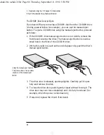
Page 78: ...anual eject button is inside a small hole in the front of the CD ROM drive 2 With a thin solid rod such as the end of a paper clip push the drive s manual eject button 3 The drive door is released opening slightly Carefully pull it open fully and retrieve the disk 4 To close the drive door push it gently closed without forcing it The drive door may not close completely until it is fully functional...

Page 79: ...accessory board has been firmly installed in the slot Check that the accessory board has been correctly configured Check that the accessory board is not using memory I O addresses an IRQ or DMA also used by the PC Workstation Refer to IRQs DMAs and I O Addresses Used by Your PC Workstation on page 82 for more information ashaki bk ashak 3 fb4 Page 69 Thursday September 10 1998 5 58 PM ...

Page 80: ... Setup 6 Select from Security the User Password submenu and set a new User password 7 Press F3 to save the new User password and exit Setup If you forget both the Hardware User and Administrator passwords 1 Switch off the PC Workstation and remove the computer s cover refer to page 3 2 Set switch 7 PSWRD on the system board switch block to ON DOWN Refer to page 85 for the switch location 3 Replace...

Page 81: ... the battery is discharged The on board battery automatically recharges itself as soon as the PC Workstation is plugged into a power outlet To change the date and time use your operating system utilities or the Setup program by pressing F2 at startup If You Have a Network Problem If you have a problem with your PC Workstation s network run the HPIEDIAG utility provided on the HP CD ROM that contai...

Page 82: ...e 4 Change to the DIAG directory by typing CD LAN DIAG Enter 5 Start the HPIEDIAG utility by typing HPIEDIAG Follow the instructions on the screen Then check the configuration of the integrated Ethernet interface using the Setup program Refer also to the Network Administrator s Guide downloadable from HP s Web site at http www hp com go kayaksupport ashaki bk ashak 3 fb4 Page 72 Thursday September...

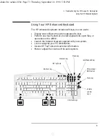
Page 83: ...uch shortcuts to start applications open files or open sites on the WWW Launch the Internet browser supplied with your system Lock or suspend your PC Workstation Access HP TopTools and customer information Mute or adjust the volume of the audio system Menu key Lock Suspend key Internet key HP TopTools Shortcut key HP Customer Information Volume control keys Shortcut keys Mute key ashaki bk ashak 3...

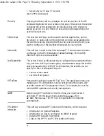
Page 84: ...ock Suspend Key The action of the Lock Suspend key is configured by pressing the Menu Key and then clicking on Configure the Extended Keys tab and the onscreen Lock button With HP Lock installed the actions you can specify for the Lock Suspend key are Launch screen saver Lock the front panel HP TopTools Pressing this soft key opens HP TopTools This application helps you manage your PC Workstation ...

Page 85: ...ing the Mute key mutes the audio or restores the audio if it has been muted The Volume keys can be used to control the volume level For more information on controlling audio on your system refer to the Using Sound guide preloaded on your PC Workstation ashaki bk ashak 3 fb4 Page 75 Thursday September 10 1998 5 58 PM ...

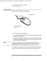
Page 86: ...zoom out reduce by holding the Ctrl key down and pushing it backwards NOTE The scroll functions only work in Windows NT and Windows 95 applications that support scrolling The zoom function works only in Microsoft Office 97 compatible applications that support zoom To change the mouse setup click the Start button select Settings Control Panel double click Mouse and select the Buttons tab Context Me...

Page 87: ...echnical Information This chapter provides technical information about your PC Workstation and includes information on the HP Setup program ashaki bk ashak 4 fb4 Page 77 Thursday September 10 1998 5 58 PM ...

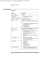
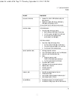
Page 88: ...combined LAN SCSI PCI board WOL Wake On LAN capability Audio Embedded Sound Blaster Pro compatible 16 bit full duplex stereo audio solution MPC 3 compatible and Direct Sound V certified Built in speaker Midi joystick interface headphones line input and line output Disk drive controllers Dual Ultra ATA 33 IDE controllers On selected models an UltraWide 16 bit SCSI controller on a combined LAN SCSI ...

Page 89: ...f height 5 25 inch drives Two internal 3 5 inch hard disk drives System board connectors One floppy disk drive connector Two ATA 33 IDE connectors for up to four IDE devices Audio connector Desktop models only Either Single front panel connector for both LCD and status panel desktop or Two front panel connectors minitower HP external start connector WOL Wake On LAN external start connector Externa...

Page 90: ...ystem with multiple temperature regulated fans to optimize cooling Headset Stereo headset with microphone SCSI Selected Models Only UltraWide 16 bit SCSI controller on a combined LAN SCSI PCI board Feature Description ashaki bk ashak 4 fb4 Page 80 Thursday September 10 1998 5 58 PM ...

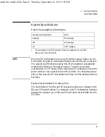
Page 91: ...e a power block with a switch You should be aware that in this case the PC Workstation will lose its time settings within a few days Maximum Loads Available for Accessory Slots The load limits for the ISA and PCI accessory slots are compliant with ISA and PCI specifications For example your PC Workstation has been designed to support up to 15W per PCI slot and a total of 60W for all 4 PCI slots 1 ...

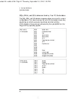
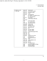
Page 92: ...S or the Plug and Play operating system IRQs used by PC Workstation IRQ0 System timer IRQ1 Keyboard controller IRQ2 Free IRQ3 COM2 COM4 IRQ4 COM1 COM3 IRQ5 LPT2 IRQ6 Floppy disk drive controller IRQ7 LPT1 IRQ8 Real time clock IRQ9 IRQ10 IRQ11 IRQ12 Mouse IRQ13 Not connected IRQ14 Integrated IDE controller IRQ15 Integrated IDE controller DMAs used by PC Workstation DMA 0 Capture DMA 1 Playback DMA ...

Page 93: ...ntroller 00C0 00DF DMA controller 2 00F0 00FF Coprocessor error 0170 0177 IDE secondary channel 01F0 01F7 IDE primary channel 0278 027F LPT 2 02E8 02EF Serial port 4 COM4 02F8 02FF Serial port 2 COM2 0372 0377 Free Secondary floppy disk drive 0378 037A LPT1 03B0 03DF VGA 03E8 03EF COM3 03F0 03F5 Floppy disk drive controller 03F6 IDE primary channel 03F7 Floppy disk drive controller 03F8 03FF COM1 ...

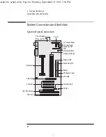
Page 94: ...ctors PCI fan External Start DT Audio DT Status Panel Buzzer Primary IDE Memory Modules External Battery FDD Secondary IDE MT LCD Panel MT Status Panel Power Power Supply Processor Fan Processor AGP Slot PCI Slots ISA PCI Combo ISA Slot Disk Drive Fan ashaki bk ashak 4 fb4 Page 84 Thursday September 10 1998 5 58 PM ...

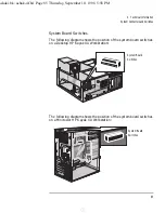
Page 95: ...gram shows the position of the system board switches on a Desktop HP Kayak XA Workstation The following diagram shows the position of the system board switches on a Minitower HP Kayak XA Workstation System Board Switches System Board Switches ashaki bk ashak 4 fb4 Page 85 Thursday September 10 1998 5 58 PM ...

Page 96: ...Speed Processor Speed UP1 UP DOWN DOWN 100 MHz 350 MHz UP DOWN UP UP 100 MHz 400 MHz UP DOWN UP DOWN 100 MHz 450 MHz UP DOWN DOWN UP 100 MHz 500 MHz Switch1 Use Switch to 1 RESERVED Do not use 6 CLEAR CMOS Retain or clear CMOS memory UP to retain CMOS memory DEFAULT DOWN to clear CMOS memory 7 PSWRD Enable or clear and disable User and System Administrator Passwords stored in EEPROM UP to enable p...

Page 97: ...FF and DOWN ON 9 BOX DEFINITION Select box type UP to select a Minitower model DOWN to select a Desktop model DEFAULT 10 BIOS Recovery Mode UP to enable normal mode DEFAULT DOWN to enable recovery mode Switch1 Use Switch to ashaki bk ashak 4 fb4 Page 87 Thursday September 10 1998 5 58 PM ...

Page 98: ... the start up logo appears on your display press Esc This takes you to the HP Summary Screen To go immediately into the Setup program and bypass the Summary Screen press F2 instead of Esc The Summary Screen is displayed for only a short time To retain the screen until you decide to leave it press F5 Starting the HP Setup Program 1 Turn on the display and then the computer If the PC Workstation is ...

Page 99: ...station 2 Disabling the LAN card will only disable certain features of the LAN card such as remote power on or remote wakeup not the card itself Network Setup Items1 Where to find in Setup Enable the integrated network interface 2 In the Advanced menu go to the Integrated Network Interface submenu Enable your PC Workstation to be started booted and logged on from the network In the Security menu g...

Page 100: ...OM line Press F7 or F8 to change the option to Disabled c Press the down arrow key to go to the Start From IDE HDD line Press F7 or F8 to change the option to Disabled 5 Save your changes and exit Selecting the Boot Device Priority You can determine the order in which your PC Workstation looks for boot devices including boot devices on the network To do this 1 With the Setup program running use th...

Page 101: ...nt panel mic connector on system board 84 H hard disk troubleshooting 65 hard disk drive cables 12 19 39 41 completing installation 16 43 hardware password if you forget 70 HP customer information key 74 HP MaxiLife 52 HP Setup program 88 HP Summary screen 88 HP TopTools 74 I I O addresses used by PC Workstation 82 IDE drive cables 12 19 39 41 45 installation completing for CD ROM 20 47 completing...

Page 102: ...lume 75 software troubleshooting 70 specifications technical 77 starting changing the boot device 90 status panel connector 84 summary screen 88 supported HP accessories 2 26 switches on system board 85 System 84 system board 84 CD connector 84 connectors 84 front panel mic 84 ISA slots 84 multimedia front panel connector 84 PCI slots 84 power connector 84 processor sockets 84 switches 85 system h...

Page 103: ... inches by 16 3 inches Footprint Desktop model 0 2 m2 2 15 sq ft Minitower model 0 09 m2 0 95 sq ft Storage temperature 40 C to 70 C 40 F to 158 F Storage humidity 8 to 80 relative Operating temperature 5 C to 40 C 40 F to 104 F Operating humidity 15 to 80 relative Acoustic noise emission Sound Power idle mode Sound Pressure idle mode as defined ISO 7779 LwA 47 dB Desktop 51 dB Minitower LpA 40 dB...

Page 104: ...t Help Contents Operating System User s Guide HP User s Guide How to Install Accessories Inside Your PC Workstation summary information only This guide downloadable from http www hp com go kayaksupport HP User s Guide HP Support and Information Services Find out about the different support options available and how to troubleshoot your PC Workstation HP User s Guide HP Support and Information Serv...

Reviews: