4
Programming Reference Guide
Setting up the Reader
Follow the steps in this section to connect and get your reader up and commu-
nicating with its host.
1. Install the interface cable.
2. Select the interface type (see page 15).
3. Configure the reader starting on page 15 (optional, depends on settings
needed).
Install the Interface Cable
The reader kit you ordered to match your interface should provide a compatible
cable for your installation. If not, contact
your HP reseller.
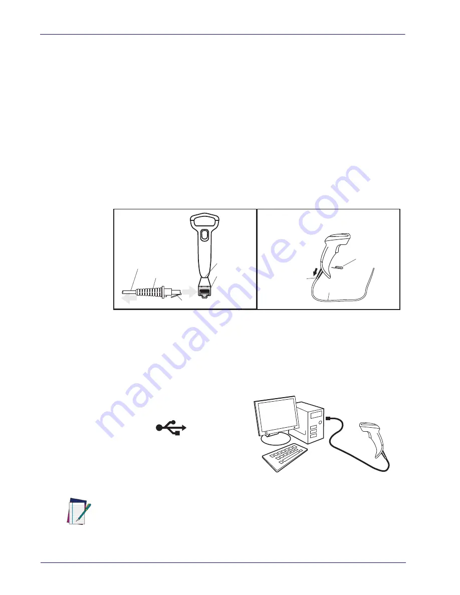
Seat the cable assembly into the reader, aligning the connector and the cable
clip as shown in the insert portion of Figure 1.
Figure 1. Connecting/Disconnecting the Interface Cable
Host connection types are described below and illustrated in Figure 2.
USB Connection:
Connect the reader to a USB port on the terminal/PC using the
correct USB cable for the interface type you ordered.
Figure 2. USB Connection
Cable Clip (Latch)
To Host
Cable
Connecting at
the Reader
Disconnecting at
the Reader
Cable Strain Relief
Bottom of Imager
Interface Cable Port
Insert a paperclip
into this hole to
release the
cable latch
Strain Relief
Cable
USB
NOTE
Specific cables are required for connection to different hosts. The connection illustrated
above is an example only. Actual connectors may vary from those illustrated, but the steps to
connect the reader remain the same.
Summary of Contents for Linear Barcode Scanner II
Page 1: ...HP Linear Barcode Scanner II Programming Reference Guide ...
Page 10: ...viii Programming Reference Guide ...
Page 240: ...Symbologies 230 Programming Reference Guide NOTES ...
Page 288: ...278 Programming Reference Guide Code 32 Codabar Code 93 Code 11 ...
Page 290: ...280 Programming Reference Guide NOTES ...
Page 292: ...282 Programming Reference Guide 6 7 8 9 ...
Page 293: ...Programming Reference Guide 283 A B C D E F ...
Page 294: ...284 Programming Reference Guide NOTES ...
Page 306: ......


