


Troubleshooting 69
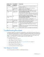
Item
See
3
"General memory problems are occurring (on page
81
)"
4
•
"Hardware problems (on page
71
)"
•
Server maintenance and service guide, located on the Easy Set-up CD,
the support CD, or the HP website
(
http://www.hp.com/products/servers/platforms
)
5
"General diagnosis flowchart (on page
62
)"
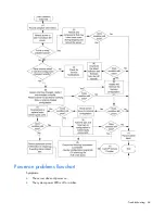
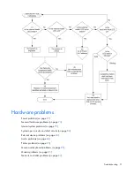
Server fault indications flowchart
Symptom: Server boots, but the internal health LED or external health LED is red or amber.


