background image


Component and LED identification  61 

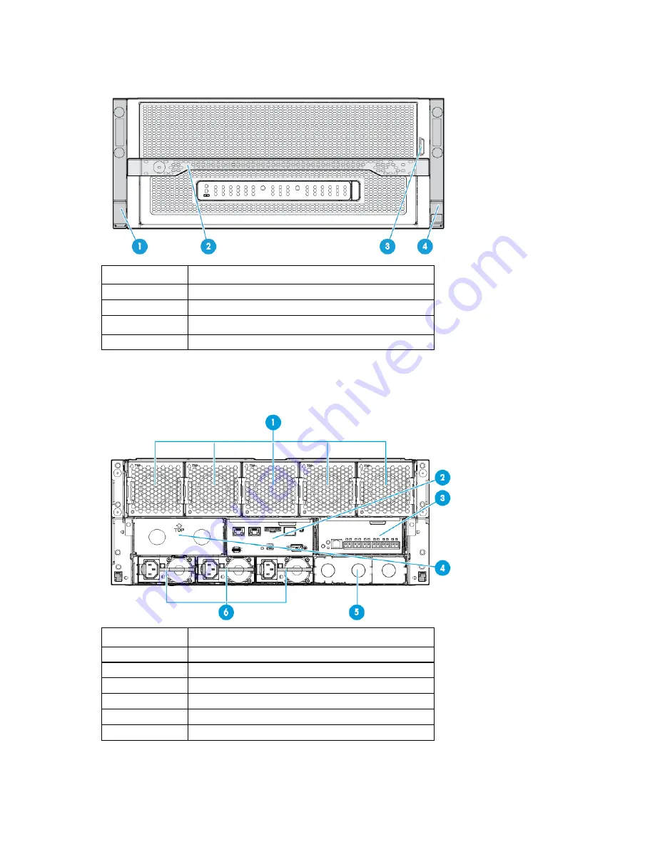
Chassis front panel components 


Item 

Description 

Bezel ear 

Backplane assembly release lever 

Serial label pull tab 

Bezel ear 


Chassis rear panel components 


Item 

Description 

Fans (5) 

Moonshot 1500 CM module 

Uplink module A 

Uplink module B (blank installed) 

Power supply blank 

Power supplies 


Summary of Contents for Moonshot 1500

Page 1: ...specifications for hardware components and software for the HP Moonshot 1500 Chassis This guide is for an experienced service technician HP assumes you are qualified in the servicing of computer equipment trained in recognizing hazards in products and are familiar with weight and stability precautions Part Number 711770 007 April 2015 Edition 7 ...

Page 2: ...e without notice The only warranties for HP products and services are set forth in the express warranty statements accompanying such products and services Nothing herein should be construed as constituting an additional warranty HP shall not be liable for technical or editorial errors or omissions contained herein ...

Page 3: ...hassis into the rack 26 Power up the chassis 29 Log in to the iLO CM firmware 30 Safety considerations 30 Preventing electrostatic discharge 30 Symbols on equipment 30 Warnings and cautions 31 Fans 31 Power supply blank 32 Power supply 33 Uplink module blank 33 Rear blank 34 HP Moonshot 1500 Chassis Management Module 35 Blanking panel 36 Switch module blank 37 Cartridge blank 38 Front chassis blan...

Page 4: ...s 61 Fan bay numbering 62 Fan LED 62 Power supply bay numbering 62 Power supply LED 63 Uplink module connectors and LEDs 63 HP Moonshot 1500 Chassis Management module LEDs and buttons 68 HP Moonshot 1500 Chassis Management module components 69 Chassis internal components 69 Cartridge slot and switch module bay identification 70 Cartridge LEDs and buttons 71 Switch module button sensor and LEDs 72 ...

Page 5: ...n will help you over the telephone HP specifies in the materials shipped with a replacement CSR part whether a defective part must be returned to HP In cases where it is required to return the defective part to HP you must ship the defective part back to HP within a defined period of time normally five 5 business days The defective part must be returned with the associated documentation in the pro...

Page 6: ...ine la société de courses ou le transporteur à utiliser Pour plus d informations sur le programme CSR de HP contactez votre Mainteneur Agrée local Pour plus d informations sur ce programme en Amérique du Nord consultez le site Web HP http www hp com go selfrepair Service de garantie pièces seules Votre garantie limitée HP peut inclure un service de garantie pièces seules Dans ce cas les pièces de ...

Page 7: ... Self Repair um Reparaturzeiten zu minimieren und höhere Flexibilität beim Austausch defekter Bauteile zu ermöglichen Wenn HP oder ein HP Servicepartner bei der Diagnose feststellt dass das Produkt mithilfe eines CSR Teils repariert werden kann sendet Ihnen HP dieses Bauteil zum Austausch direkt zu CSR Teile werden in zwei Kategorien unterteilt Zwingend Teile für die das Customer Self Repair Verfa...

Page 8: ...tegorías Obligatorio componentes para los que la reparación por parte del usuario es obligatoria Si solicita a HP que realice la sustitución de estos componentes tendrá que hacerse cargo de los gastos de desplazamiento y de mano de obra de dicho servicio Opcional componentes para los que la reparación por parte del usuario es opcional Estos componentes también están diseñados para que puedan ser r...

Page 9: ...orieën CSR onderdelen Verplicht Onderdelen waarvoor reparatie door de klant verplicht is Als u HP verzoekt deze onderdelen voor u te vervangen worden u voor deze service reiskosten en arbeidsloon in rekening gebracht Optioneel Onderdelen waarvoor reparatie door de klant optioneel is Ook deze onderdelen zijn ontworpen voor reparatie door de klant Als u echter HP verzoekt deze onderdelen voor u te v...

Page 10: ...ependendo do tipo de serviço de garantia destinado ao produto OBSERVAÇÃO Algumas peças da HP não são projetadas para o reparo feito pelo cliente A fim de cumprir a garantia do cliente a HP exige que um técnico autorizado substitua a peça Essas peças estão identificadas com a marca No Não no catálogo de peças ilustrado Conforme a disponibilidade e o local geográfico as peças CSR serão enviadas no p...

Page 11: ...Customer self repair 11 No caso desse serviço a substituição de peças CSR é obrigatória Se desejar que a HP substitua essas peças serão cobradas as despesas de transporte e mão de obra do serviço ...

Page 12: ...Customer self repair 12 ...

Page 13: ...Customer self repair 13 ...

Page 14: ...Customer self repair 14 ...

Page 15: ...el 736389 001 Mandatory1 4 Switch module blank 726173 001 Mandatory1 5 Uplink module blank 745288 001 Mandatory1 6 Power supply blank 745827 001 Mandatory1 7 Rear blank for unused chassis bay 745289 001 Mandatory1 8 Front chassis blank 712677 001 Mandatory1 9 Rear back flow preventer 747030 001 Mandatory1 10 Fan louver 689260 001 Optional2 11 Midplane cover 745826 001 Mandatory1 12 Rack rail adapt...

Page 16: ...azione da parte del cliente Per rispettare la garanzia HP richiede che queste parti siano sostituite da un centro di assistenza autorizzato Tali parti sono identificate da un No nel Catalogo illustrato dei componenti 1 Mandatory Zwingend Teile die im Rahmen des Customer Self Repair Programms ersetzt werden müssen Wenn Sie diese Teile von HP ersetzen lassen werden Ihnen die Versand und Arbeitskoste...

Page 17: ...peças serão cobradas as despesas de transporte e mão de obra do serviço 2 Optional Opcional Peças cujo reparo feito pelo cliente é opcional Essas peças também são projetadas para o reparo feito pelo cliente No entanto se desejar que a HP as substitua pode haver ou não a cobrança de taxa adicional dependendo do tipo de serviço de garantia destinado ao produto 3 No Nenhuma Algumas peças da HP não sã...

Page 18: ...85 001 Mandatory1 b 1500 W Platinum Plus 94 704604 001 Mandatory1 c 1500 W CS 48VDC HTPLG 794734 001 Mandatory1 21 Fans a Fan module for chassis with HP part number 700349 B21 or 700350 B21 689253 001 Mandatory1 b Fan module for chassis with HP part number 740872 B21 or 747049 B21 745290 001 Mandatory1 22 Midplane assembly 736390 001 Optional2 23 AC power cord IEC IEC 6 ft 142258 001 Mandatory1 24...

Page 19: ... deve sostenere le spese di spedizione e di manodopera per il servizio 2 Optional Opzionali Parti la cui riparazione da parte del cliente è facoltativa Si tratta comunque di componenti progettati per questo scopo Se tuttavia il cliente ne richiede la sostituzione ad HP potrebbe dover sostenere spese addizionali a seconda del tipo di garanzia previsto per il prodotto 3 No Non CSR Alcuni componenti ...

Page 20: ...r een geautoriseerde Service Partner worden vervangen Deze onderdelen worden in de geïllustreerde onderdelencatalogus aangemerkt met Nee 1 Mandatory Obrigatória Peças cujo reparo feito pelo cliente é obrigatório Se desejar que a HP substitua essas peças serão cobradas as despesas de transporte e mão de obra do serviço 2 Optional Opcional Peças cujo reparo feito pelo cliente é opcional Essas peças ...

Page 21: ...on page 23 Remove the access panel on page 24 Remove the chassis from the rack on page 25 Install the access panel on page 26 Install the chassis into the rack on page 26 Power up the chassis on page 29 Log in to the iLO CM firmware on page 30 Power down the chassis CAUTION The Chassis UID flashes if a firmware update is occurring in the system A switch or cartridge UID flashes if that target unde...

Page 22: ...n Disconnect the cable management arm Before removing the chassis from the rack you must first disconnect the cable management arm 1 Power down the chassis on page 21 2 Open the cable management arm on page 22 3 Remove all power a Disconnect each power cord from the power source b Disconnect each power cord from the chassis 4 Disconnect all peripheral devices from the chassis ...

Page 23: ...y or equipment damage be sure that the rack is adequately stabilized before extending a component from the rack 2 Extend the chassis from the rack until it locks once 3 Press the push tab on the rail and then fully extend the chassis WARNING To reduce the risk of personal injury be careful when pressing the server rail release latches and sliding the server into the rack The sliding rails could pi...

Page 24: ...assis when complete Do not operate the chassis for long periods of time with the access panel removed IMPORTANT To maintain appropriate cooling fans will operate at a high speed when the access panel is removed IMPORTANT When the access panel is removed the cartridge might be placed into a low power operating state to reduce thermal stress To remove the component 1 If the locking latch is locked u...

Page 25: ...r removal especially when the chassis is not installed in the rack An additional person may be required to help align the chassis if the chassis is installed higher than chest level Observe local occupational health and safety requirements and guidelines for manual material handling HP recommends removing all installed components from the chassis before installing or moving the chassis To remove t...

Page 26: ...ack WARNING The chassis is very heavy To reduce the risk of personal injury or damage to the equipment do the following Observe local occupational health and safety requirements and guidelines for manual material handling Get help to lift and stabilize the product during installation or removal especially when the product is not fastened to the rails The chassis weighs more than 81 65 kg 180 00 lb...

Page 27: ...duct parallel to the floor when installing the chassis Tilting the product up or down could result in damage to the slides CAUTION HP has not tested or validated the HP Moonshot 1500 Chassis with any third party racks Before installing the HP Moonshot 1500 Chassis in a third party rack be sure to properly scope the limitations of the rack Before proceeding with the installation consider the follow...

Page 28: ... the product pieces during assembly installation or removal especially when the chassis is not installed in the rack An additional person may be required to help align the chassis if the chassis is installed higher than chest level Observe local occupational health and safety requirements and guidelines for manual material handling HP recommends removing all installed components from the chassis b...

Page 29: ... the Push tab on each rail again when the rails lock at a 76 2 cm 30 inch extension Then release the Push tabs again and finish sliding the chassis into the rack Failure to release the Push tabs may cause damage to the rails Power up the chassis If the chassis was powered off while installing the cartridge then power up the chassis The cartridges are hot pluggable and do not require that you power...

Page 30: ...e procedures review all the safety information Preventing electrostatic discharge To prevent damaging the system be aware of the precautions you need to follow when setting up the system or handling parts A discharge of static electricity from a finger or other conductor may damage system boards or other static sensitive devices This type of damage may reduce the life expectancy of the device To p...

Page 31: ...n power supplies or systems indicate that the equipment is supplied by multiple sources of power WARNING To reduce the risk of injury from electric shock remove all power cords to completely disconnect power from the system Warnings and cautions Before installing a chassis be sure that you understand the following warnings and cautions WARNING To reduce the risk of electric shock or damage to the ...

Page 32: ...rflow in the chassis Be sure to order the correct fan spare part number for your chassis For more information see System components on page 18 To remove the component 1 Open the cable management arm on page 22 2 Squeeze the two release tabs on the fan together to release it from the chassis 3 Remove the component as indicated To replace the component reverse the removal procedure Power supply blan...

Page 33: ...nt or a component blank is always installed in each bay in the rear of chassis When replacing a component or blank leave the bay empty for no more than 60 seconds Failure to do so can disrupt airflow in the chassis To remove the component 1 Open the cable management arm on page 22 2 Remove the component as indicated To replace the component reverse the removal procedure Uplink module blank ...

Page 34: ...s To remove the component 1 Open the cable management arm on page 22 2 Remove the component as indicated To replace the component reverse the removal procedure Rear blank CAUTION For proper cooling be sure that a component or a component blank is always installed in each bay in the rear of chassis When replacing a component or blank leave the bay empty for no more than 60 seconds Failure to do so ...

Page 35: ...n 60 seconds Failure to do so can disrupt airflow in the chassis CAUTION Removing the Moonshot 1500 CM module results in the loss of remote management connectivity for the chassis and both switches Before removing the module be sure no remote sessions are in progress CAUTION The Chassis UID flashes if a firmware update is occurring in the system The HP Moonshot 1500 Chassis Management Module shoul...

Page 36: ...placement procedures 36 3 Remove the component as indicated To replace the component reverse the removal procedure Blanking panel Remove the component as indicated To replace the component 1 Align the blanking panel ...

Page 37: ...g be sure that a cartridge or a cartridge blank is always installed in each cartridge slot in the chassis When replacing a cartridge leave the cartridge slot empty for no more than 30 seconds Failure to do so can disrupt airflow in the chassis To remove the component 1 Extend the chassis from the rack on page 23 2 Remove the access panel on page 24 3 Remove the component as indicated ...

Page 38: ...a cartridge leave the cartridge slot empty for no more than 30 seconds Failure to do so can disrupt airflow in the chassis To remove the component 1 Extend the chassis from the rack on page 23 2 Remove the access panel on page 24 3 Remove the cartridge blank from the chassis To replace the component reverse the removal procedure Front chassis blank To remove the component 1 Extend the chassis from...

Page 39: ...emove the component 1 Power down the chassis on page 21 2 Open the cable management arm on page 22 3 Remove all power a Disconnect each power cord from the power source b Disconnect each power cord from the chassis 4 Disconnect all peripheral devices from the chassis 5 Extend the chassis from the rack on page 23 6 Remove the access panel on page 24 ...

Page 40: ...edure Fan louver To remove the component 1 Power down the chassis on page 21 2 Open the cable management arm on page 22 3 Remove all power a Disconnect each power cord from the power source b Disconnect each power cord from the chassis 4 Disconnect all peripheral devices from the chassis 5 Extend the chassis from the rack on page 23 6 Remove the access panel on page 24 7 Remove the midplane cover ...

Page 41: ...2 Open the cable management arm on page 22 3 Remove all power a Disconnect each power cord from the power source b Disconnect each power cord from the chassis 4 Disconnect all peripheral devices from the chassis 5 Extend the chassis from the rack on page 23 6 Remove the access panel on page 24 7 Remove the midplane cover Midplane cover on page 39 8 Disconnect the fan cable from each end of the mid...
Page 42: ...ear backflow preventer To remove the component 1 Power down the chassis on page 21 2 Open the cable management arm on page 22 3 Remove all power a Disconnect each power cord from the power source b Disconnect each power cord from the chassis 4 Remove the fans directly above the bay to be serviced Fans on page 31 5 Remove the uplink module or uplink module blank from the bay to be serviced ...

Page 43: ...ews that secure the rear back flow preventer to the chassis and slide the rear back flow preventer towards the midplane tilting at an angle to remove To replace the component reverse the removal procedure Bezel ear To remove the component 1 Power down the chassis on page 21 2 Open the cable management arm on page 22 3 Remove all power a Disconnect each power cord from the power source b Disconnect...

Page 44: ...Removal and replacement procedures 44 7 Use a T 10 Torx screwdriver to remove the three screws securing the bezel ear to the chassis ear 8 Remove the right bezel ear ...

Page 45: ...onent reverse the removal procedure Discovery Services midplane cable To remove the component 1 Power down the chassis on page 21 2 Open the cable management arm on page 22 3 Remove all power a Disconnect each power cord from the power source b Disconnect each power cord from the chassis 4 Extend the chassis from the rack on page 23 ...

Page 46: ...39 8 Remove the discovery services midplane cable cover to access the cable 9 Disconnect the Discovery Services midplane cable from the midplane and remove it from the chassis To replace the component reverse the removal procedure Front panel display To remove the component 1 Power down the chassis on page 21 2 Open the cable management arm on page 22 3 Remove all power ...

Page 47: ...ord from the power source b Disconnect each power cord from the chassis 4 Release the front panel display 5 Disconnect the front panel display cable and remove the front panel display To replace the component reverse the removal procedure Front panel display cable ...

Page 48: ... installed components from the chassis before installing or moving the chassis IMPORTANT Make note of the cartridge and switch locations before removing them The cartridges and switches must be returned to their original locations To remove the component 1 Power down the chassis on page 21 2 Open the cable management arm on page 22 3 Remove all power a Disconnect each power cord from the power sou...

Page 49: ...ove each switch module or switch module blank from the chassis 13 Remove the chassis from the rack on page 25 14 Place the chassis on a flat sturdy surface to support the chassis 15 Remove the front panel display Front panel display on page 46 16 Remove the backplane assembly Backplane assembly on page 50 ...

Page 50: ... An additional person may be required to help align the chassis if the chassis is installed higher than chest level Observe local occupational health and safety requirements and guidelines for manual material handling HP recommends removing all installed components from the chassis before installing or moving the chassis IMPORTANT Make note of the cartridge and switch locations before removing the...

Page 51: ...HP Moonshot 1500 Chassis Management Module HP Moonshot 1500 Chassis Management Module on page 35 7 Remove the fans Fans on page 31 8 Remove the power supplies 9 Extend the chassis from the rack on page 23 10 Remove the access panel on page 24 11 Remove each cartridge or cartridge blank from the chassis ...

Page 52: ...module blank from the chassis 13 Remove the chassis from the rack on page 25 14 Place the chassis on a flat sturdy surface to support the chassis 15 Remove the midplane cover Midplane cover on page 39 16 Pull up on the backplane release lever to disengage the backplane assembly ...

Page 53: ... installed in the rack An additional person may be required to help align the chassis if the chassis is installed higher than chest level Observe local occupational health and safety requirements and guidelines for manual material handling HP recommends removing all installed components from the chassis before installing or moving the chassis IMPORTANT All components must be removed to service the...

Page 54: ...HP Moonshot 1500 Chassis Management Module HP Moonshot 1500 Chassis Management Module on page 35 7 Remove the fans Fans on page 31 8 Remove the power supplies 9 Extend the chassis from the rack on page 23 10 Remove the access panel on page 24 11 Remove each cartridge or cartridge blank from the chassis ...

Page 55: ... sturdy surface to support the chassis 15 Remove the midplane cover Midplane cover on page 39 16 Remove the backplane assembly Backplane assembly on page 50 17 Disconnect and remove the fan cable Fan cable on page 41 18 Remove the four screws from the bottom of the chassis loosen the captive screws securing the midplane assembly to the chassis and then lift it up to access the cables ...

Page 56: ...erse the removal procedure When replacing the midplane cover be sure to do the following Align the midplane assembly carefully with the provided guides Tilt the midplane cover towards the front of the chassis and then down to align the screw holes Use a T 15 Torx screwdriver to tighten the captive screws that secure the midplane cover to the chassis ...

Page 57: ...ng Guide provides procedures for resolving common problems and comprehensive courses of action for fault isolation and identification issue resolution and software maintenance on the HP Moonshot System The document is available in the HP Moonshot Information Library http www hp com go moonshot docs ...

Page 58: ... SSH client For more information see the HP Moonshot iLO Chassis Management CLI User Guide in the HP Moonshot Information Library http www hp com go moonshot docs HP Moonshot iLO CM Event Log The iLO CM Event Log is an operating system independent log that maintains a record of events by date and time Logged events include major events such as a power outage or a reset and iLO CM firmware events T...

Page 59: ...LO Chassis Manager CLI or HP Moonshot 45G 180G Switch Module CLI or by using the included HP Smart Update Manager Download the latest pack from the HP website http www hp com go moonshot download HP Smart Update Manager HP SUM is an application included with the Moonshot Component Pack that provides a web based GUI for installing and updating firmware on many HP products including the HP Moonshot ...

Page 60: ... System firmware update is in process Off Chassis ID is not selected 4 Cartridge health LEDs Green Normal operation Amber Standby mode Flashing amber Degraded condition Flashing amber All Moonshot 1500 CM module is not installed Flashing red Critical condition Off Cartridge is not installed or no power exists 5 Switch module A health LED Green Normal operation Flashing amber Degraded condition Fla...

Page 61: ...tem Description 1 Bezel ear 2 Backplane assembly release lever 3 Serial label pull tab 4 Bezel ear Chassis rear panel components Item Description 1 Fans 5 2 Moonshot 1500 CM module 3 Uplink module A 4 Uplink module B blank installed 5 Power supply blank 6 Power supplies ...

Page 62: ...Component and LED identification 62 Fan bay numbering Fan LED Status Description Off The fan is working or the power is off Solid amber The fan has failed Power supply bay numbering ...

Page 63: ...ed Power supply failure includes overvoltage overcurrent and overtemperature Green Power is present and main 12 V output is enabled Uplink module connectors and LEDs The uplink module is installed on the rear of the chassis in uplink module bay A or B The uplink module LEDs and components only operate as described in this section if the corresponding switch module is also installed ...

Page 64: ... or 10Gb Ethernet SFP ports X1 through X6 support Ethernet traffic only SFP ports support the following pluggable Ethernet transceiver modules HP 1000BASE T SFP HP 1000BASE SX SFP HP 10GBASE SR SFP HP 10GBASE DAC SFP Any available port can be used to connect to the data center Ensure the port is populated with supported HP transceiver modules that are compatible with the data center port type ...

Page 65: ...le firmware update is in progress Off Switch module ID is not selected 2 Uplink module health LED Green Normal operation Flashing amber Degraded condition Flashing red Critical condition Off No power 3 Uplink module link LED Solid green Link Off No link 4 Uplink module activity LED Flashing green Activity Off No activity 5 Reset button Resets the switch module Moonshot 4QSFP Uplink Module componen...

Page 66: ...s populated with supported HP transceiver modules that are compatible with the data center port type Moonshot 4QSFP Uplink Module LEDs and buttons Item Description Status 1 Uplink module UID LED button Solid blue Switch module ID is selected Flashing blue Switch module firmware update is in progress Off Switch module ID is not selected 2 Uplink module health LED Green Normal operation Flashing amb...

Page 67: ...y The following cables and transceiver modules are supported HP 10GBASE DAC SFP HP 10GBASE SR SFP HP 1000BASE T SFP HP 1000BASE SX SFP Use any available port to connect to the data center Be sure the port is populated with a supported HP transceiver module that is compatible with the data center switch port type For a list of supported transceivers see the product QuickSpecs Moonshot 16SFP Uplink ...

Page 68: ...nk activity LED Off No link Solid green 10Gb link Blinking green Active 10Gb traffic Solid amber 1Gb link Blinking amber Active 1Gb traffic 5 Top port link activity LED Off No link Solid green 10Gb link Blinking green Active 10Gb traffic Solid amber 1Gb link Blinking amber Active 1Gb traffic HP Moonshot 1500 Chassis Management module LEDs and buttons Item Description Label 1 iLO CM management port...

Page 69: ... link port disabled by default LINK 3 Moonshot 1500 CM module HP APM port RCM 4 Moonshot 1500 CM module diagnostic port DEBUG 5 iLO CM management serial port 6 Moonshot 1500 CM module USB connector 7 Moonshot 1500 CM module MicroSD slot Chassis internal components Up to 45 cartridges and two switch modules can be installed in the HP Moonshot 1500 Chassis ...

Page 70: ...Component and LED identification 70 Cartridge slot and switch module bay identification The chassis provides 45 cartridge slots 1 45 and two switch module bays A B ...

Page 71: ...al condition Off No power 3 Drive LED Green Activity Off No activity 4 Cartridge UID LED button Blue Cartridge ID is selected Flashing blue Cartridge firmware update is in progress Off Cartridge ID is not selected 5 Cartridge link LED button Flashing white Cartridges are linked Off Cartridge is not linked to other cartridges Depending on the cartridge installed there might be 0 1 or 2 drive LEDs T...

Page 72: ...Off No power 3 Switch module uplink activity LED Green Link Flashing green Activity Off No activity 4 Switch module downlink activity LED Green Link Flashing green Activity Off No activity 5 Switch module UID LED button Solid blue Switch module ID is selected Flashing blue Switch module firmware update is in progress Off Switch module ID is not selected 6 Access panel sensor Detects the presence o...

Page 73: ... level An altitude derating of 1 C per 304 8 m 1 8 F per 1000 ft to 3048 m 10 000 ft is applicable No direct sunlight allowed Upper operating limit is 3 048 m 10 000 ft or 70 kPa 10 1 psia Upper non operating limit is 9 144 m 30 000 ft Storage maximum humidity of 95 is based on a maximum temperature of 45 C 113 F Altitude maximum for storage corresponds to a pressure minimum of 70 kPa 10 1 psia Ch...

Page 74: ...Management CLI User Guide in the HP Moonshot Information Library http www hp com go moonshot docs HP contact information For United States and worldwide contact information see the Contact HP website http www hp com go assistance In the United States To contact HP by phone call 1 800 334 5144 For continuous quality improvement calls may be recorded or monitored If you have purchased a Care Pack se...

Page 75: ...nagement Utility CSR Customer Self Repair DAC direct attach cable HP APM HP Advanced Power Manager iLO Integrated Lights Out IML Integrated Management Log IPMI Intelligent Platform Management Interface PDU power distribution unit RCM Remote Console Module SFP small form factor pluggable SR short range ...

Page 76: ...Acronyms and abbreviations 76 SSH Secure Shell UID unit identification UPS uninterruptible power system ...

Page 77: ...oviding documentation that meets your needs To help us improve the documentation send any errors suggestions or comments to Documentation Feedback mailto docsfeedback hp com Include the document title and part number version number or the URL when submitting your feedback ...

Page 78: ...k 23 chassis remove from rack 25 CMU 58 75 components 15 60 61 69 components identification 15 18 60 components mechanical 15 components server 15 components uplink module 64 65 67 contact information 74 contacting HP 74 CSR customer self repair 5 customer self repair CSR 5 74 D diagnosing problems 57 dimensions and weight 73 downloading files 74 drive health LED 71 E electrostatic discharge 30 en...

Page 79: ...63 LEDs troubleshooting 57 60 LEDs unit identification UID 60 72 LEDs uplink module 63 65 66 67 link LED 71 M management module 35 management module components 69 management module connectors 68 management module LEDs 68 mechanical components 15 microSD card slot 69 midplane 18 53 midplane cover 39 Moonshot 1500 CM module 18 35 61 Moonshot 1500 CM module components 69 Moonshot 1500 CM module diagn...

Page 80: ... bay numbering 70 switch module blank 37 symbols on equipment 30 system components 18 T technical support 5 74 telephone numbers 74 troubleshooting 57 troubleshooting resources 57 troubleshooting firmware upgrade utility 57 U UID button 68 71 UID LED 68 71 uplink module 18 33 63 64 65 66 67 uplink module blank 33 uplink module components 64 65 67 USB connector 69 utilities 58 W warnings 31 website...

Reviews: