363
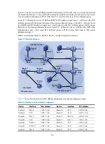
Figure 98
Network diagram
shows the interface and IPv6 address assignment, and network topology scheme.
Table 30
Interface and IPv6 address assignment
Device Interface
IPv6 address
Router A
Ethernet 1/1
1001::1/64
Router A
Serial 2/1
1002::1/64
Router B
Ethernet 1/1
2001::1/64
Router B
Serial 2/1
1002::2/64
Router B
Serial 2/2
2002::1/64
Router C
Serial 2/1
2002::2/64
Router C
Serial 2/2
3001::1/64
Router C
Loopback 0
6001::1/128
Router D
Ethernet 1/1
4001::1/64
Router D
Ethernet 1/2
5001::1/64
Router D
Serial 2/1
3001::2/64
Source 1
—
1001::2/64
Source 2
—
5001::2/64
Receiver 1
—
2001::2/64
Receiver 2
—
4001::2/64
Configuration procedure
1.
Enable IPv6 forwarding on each router, and configure the IPv6 address and prefix length for each
interface according to
. (Details not shown.)
2.
Configure OSPFv3 on the routers in the IPv6 BIDIR-PIM domain to ensure network-layer
reachability among them. (Details not shown.)
3.
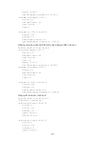
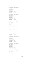
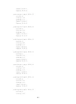
Enable IPv6 multicast routing, IPv6 PIM-SM, IPv6 BIDIR-PIM, and MLD:
IPv6 BIDIR-PIM
Source 1
Source 2
Host A
Receiver 1
Router A
S2/1
S2/1
S2/2
S2/1
S2/2
S2/1
Eth1/1
Eth1/1
Et
h1
/1
Eth1/2
Router D
Router C
Router B
Host B
Receiver 2
Loop0


