510
6.
After the authentication center starts up, the
Open AuthN Center
button changes to
Close AuthN
Center
. Click the
Close AuthN Center
to remove the RADIUS server and the guest user.
7.
Drag the icon of a specific device in the WiNet topology and place it to a position as needed. If
the browser is configured to accept cookies, the latest position information of each device is stored
after you click
Network
Snapshot
.
8.
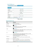
Double-click a device on the WiNet topology map to show details about the device, including the
hostname, MAC address, device model, IP address, version, number of hops, and WiNet
Figure 534
Device details
9.
View the WiNet topology information, including the role of each device and connection status
between devices. The connection status can be:
Normal link
—Indicates a connection existing in the baseline topology and the current topology.
New link
—Indicates a connection not existing in the baseline topology but in the current
topology.
Blocked loops
—Indicate connections blocked by STP. If a normal link is blocked, it is displayed
as a black broken line; if a new link is blocked, it is displayed as a blue broken line.
Down link
—Indicates a connection existing in the baseline topology but not in the current
topology.
10.
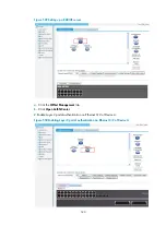
Click a device in the topology diagram to view its panel diagram. You can manage the device as
follows:
NOTE:
Support for displaying of the device panel, device renaming, and Layer 2 portal authentication on
interfaces depends on the device model.
a.
Click
Rename Device
and enter a new system name for the device.
Figure 535
Rename a device
Summary of Contents for MSR SERIES
Page 17: ...xv Documents 835 Websites 835 Conventions 836 Index 838 ...
Page 20: ...3 Figure 3 Initial page of the Web interface ...
Page 42: ...25 Figure 13 Firefox Web browser setting ...
Page 59: ...42 Figure 27 Checking the basic service configuration ...
Page 73: ...56 Figure 35 Sample interface statistics ...
Page 156: ...139 Figure 139 Rebooting the 3G modem ...
Page 168: ...151 Figure 152 Configuring Web server 2 ...
Page 174: ...157 Figure 158 Configure the URL filtering function ...
Page 242: ...225 Figure 233 Enabling the DHCP client on interface Ethernet 0 1 ...
Page 247: ...230 Figure 236 The page for configuring an advanced IPv4 ACL ...
Page 255: ...238 Figure 241 Advanced limit setting ...
Page 298: ...281 e Click Apply 2 Configure Router B in the same way Router A is configured ...
Page 400: ...383 Figure 387 Verifying the configuration ...
Page 405: ...388 ...
Page 523: ...506 Figure 530 Ping configuration page ...
Page 775: ...758 Figure 785 Configuring a jump node ...


