304
However, the newly calculated configuration BPDU will not be propagated throughout the network
immediately, so the old root ports and designated ports that have not detected the topology change
continue forwarding data along the old path. If the new root ports and designated ports begin to
forward data as soon as they are elected, a temporary loop might occur.
STP timers
STP calculation involves the following timers:
•
Forward delay
—The delay time for device state transition. A path failure can cause spanning tree
re-calculation to adapt the spanning tree structure to the change. However, the resulting new
configuration BPDU cannot propagate throughout the network immediately. If the newly elected
root ports and designated ports start to forward data right away, a temporary loop is likely to occur.
For this reason, as a mechanism for state transition in STP, the newly elected root ports or
designated ports require twice the forward delay time before transiting to the forwarding state to
make sure the new configuration BPDU has propagated throughout the network.
•
Hello time
—The time interval at which a device sends hello packets to the surrounding devices to
make sure the paths are fault free.
•
Max age
—A parameter used to determine whether a configuration BPDU held by the device has
expired. A configuration BPDU beyond the max age will be discarded.
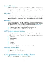
Introduction to RSTP
Developed based on the 802.1w standard of IEEE, RSTP is an optimized version of STP. It achieves rapid
network convergence by allowing a newly elected root port or designated port to enter the forwarding
state much quicker under certain conditions than in STP.
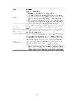
In RSTP, a newly elected root port can enter the forwarding state rapidly if this condition is met: the old
root port on the device has stopped forwarding data and the upstream designated port has started
forwarding data.
In RSTP, a newly elected designated port can enter the forwarding state rapidly if this condition is met:
the designated port is an edge port or a port connected to a point-to-point link. If the designated port is
an edge port, it can enter the forwarding state directly. If the designated port is connected to a
point-to-point link, it can enter the forwarding state immediately after the device undergoes handshake
with the downstream device and gets a response.
Introduction to MSTP
STP does not support rapid state transition of ports. A newly elected root port or designated port must
wait twice the forward delay time before transiting to the forwarding state, even if it is a port on a
point-to-point link or an edge port, which directly connects to a user terminal rather than to another
device or a shared LAN segment.
Although RSTP supports rapid network convergence, it has the same drawback as STP—All bridges
within a LAN share the same spanning tree, so redundant links cannot be blocked based on VLAN, and
the packets of all VLANs are forwarded along the same spanning tree.
MSTP features
Developed based on IEEE 802.1s, MSTP overcomes the limitations of STP and RSTP. In addition to the
support for rapid network convergence, it also allows data flows of different VLANs to be forwarded
along separate paths, providing a better load sharing mechanism for redundant links.
Summary of Contents for MSR SERIES
Page 17: ...xv Documents 835 Websites 835 Conventions 836 Index 838 ...
Page 20: ...3 Figure 3 Initial page of the Web interface ...
Page 42: ...25 Figure 13 Firefox Web browser setting ...
Page 59: ...42 Figure 27 Checking the basic service configuration ...
Page 73: ...56 Figure 35 Sample interface statistics ...
Page 156: ...139 Figure 139 Rebooting the 3G modem ...
Page 168: ...151 Figure 152 Configuring Web server 2 ...
Page 174: ...157 Figure 158 Configure the URL filtering function ...
Page 242: ...225 Figure 233 Enabling the DHCP client on interface Ethernet 0 1 ...
Page 247: ...230 Figure 236 The page for configuring an advanced IPv4 ACL ...
Page 255: ...238 Figure 241 Advanced limit setting ...
Page 298: ...281 e Click Apply 2 Configure Router B in the same way Router A is configured ...
Page 400: ...383 Figure 387 Verifying the configuration ...
Page 405: ...388 ...
Page 523: ...506 Figure 530 Ping configuration page ...
Page 775: ...758 Figure 785 Configuring a jump node ...


