474
Managing the system
Configuring Web management
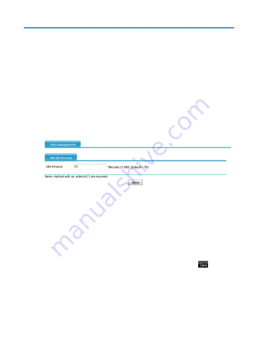
This module enables you to set the Web connection idle-timeout timer. If you do not perform any
operations on the Web interface before this timer expires, you are logged out of the Web page. By
default, the idle-timeout timer is 10 minutes.
To set an idle-timeout timer:
1.
From the navigation tree, select
System Management
>
Device Basic
.
The page for setting the idle-timeout timer appears.
2.
In the
Idle timeout
field, enter an idle-timeout timer value.
3.
Click
Apply
.
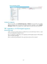
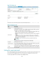
Figure 502
Setting the idle-timeout timer
Managing the configuration
Saving the configuration
This module provides the following functions:
•
Saving the current configuration to the next-startup configuration file, including the
.cfg
and
.xml
files.
•
Saving the current configuration as the factory default configuration, and the name of the
configuration file is
init.cfg
.
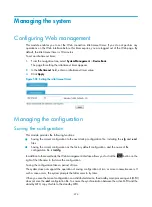
In addition to these methods, the Web management interface allows you to click the
button on the
right of the title area to fast save the configuration.
Saving the configuration takes a period of time.
The system does not support the operation of saving configuration of two or more consecutive users. If
such a case occurs, the system prompts the latter users to try later.
When you save the current configuration on a distributed device, the standby main processing unit (MPU)
does not save the
.xml
configuration file. To ensure the synchronization between the active MPU and the
standby MPU, copy this file to the standby MPU.
Summary of Contents for MSR SERIES
Page 17: ...xv Documents 835 Websites 835 Conventions 836 Index 838 ...
Page 20: ...3 Figure 3 Initial page of the Web interface ...
Page 42: ...25 Figure 13 Firefox Web browser setting ...
Page 59: ...42 Figure 27 Checking the basic service configuration ...
Page 73: ...56 Figure 35 Sample interface statistics ...
Page 156: ...139 Figure 139 Rebooting the 3G modem ...
Page 168: ...151 Figure 152 Configuring Web server 2 ...
Page 174: ...157 Figure 158 Configure the URL filtering function ...
Page 242: ...225 Figure 233 Enabling the DHCP client on interface Ethernet 0 1 ...
Page 247: ...230 Figure 236 The page for configuring an advanced IPv4 ACL ...
Page 255: ...238 Figure 241 Advanced limit setting ...
Page 298: ...281 e Click Apply 2 Configure Router B in the same way Router A is configured ...
Page 400: ...383 Figure 387 Verifying the configuration ...
Page 405: ...388 ...
Page 523: ...506 Figure 530 Ping configuration page ...
Page 775: ...758 Figure 785 Configuring a jump node ...


