background image


701 

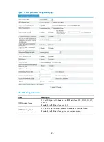
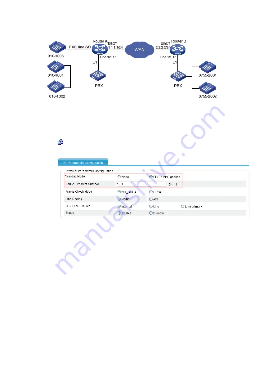
Figure 723


Network diagram 


Configuration procedure 

1.


Configure Router A: 
# Configure an ISDN PRI group. 
Select

 Voice Management

 > 

Digital Link Management

 from the navigation tree, and then click the 

 icon of 

E1 1/1

 to access the E1 parameters configuration page. 

Figure 724


E1 parameters configuration page 


a.


Select the 

PRI Trunk Signaling

 option. For other options, use the default settings. 

b.


Click 

Apply

# Configure local numbers and call routes. 

c.


Configure a local number in the local number configuration page: The number ID is 1003, the 
number is 0101003, and the bound line is 3/0. 

d.


Configure a call route in the call route configuration page: The call route ID is 1001, the 
destination number is 0101001, and the trunk route line is 1/1:15. In addition, to select the


Send All Digits of a Called Number

 option in the 

Called Number Sending Mode

 area when you 

configure the advanced settings of this call route. 

e.


Configure a call route in the call route configuration page: The call route ID is 1002, the 
destination number is 0101002, and the trunk route line is 1/1:15. In addition, select the


Send All Digits of a Called Number

 option in the 

Called Number Sending Mode

 area when you 

configure the advanced settings of this call route. 

f.


Configure a call route in the call route configuration page: The call route ID is 0755, the 
destination number is 0755...., and the call route type is SIP, the SIP routing type is IP routing, 

and the destination address is 2.2.2.2. 

2.


Configure Router B. 

Summary of Contents for MSR SERIES

Page 1: ...HP MSR Router Series Web Based Configuration Guide V5 Part number 5998 8174 Software version CMW520 R2513 Document version 6PW106 20150808 ...

Page 2: ...MATERIAL INCLUDING BUT NOT LIMITED TO THE IMPLIED WARRANTIES OF MERCHANTABILITY AND FITNESS FOR A PARTICULAR PURPOSE Hewlett Packard shall not be liable for errors contained herein or for incidental or consequential damages in connection with the furnishing performance or use of this material The only warranties for HP products and services are set forth in the express warranty statements accompan...

Page 3: ...ent system logs 28 Managing integrated services 29 Basic services configuration 30 Configuring basic services 30 Entering the homepage of basic configuration wizard 30 Setting WAN interface parameters 30 Setting LAN interface parameters 39 Setting WLAN interface parameters 40 Validating the basic services configuration 41 Configuring WAN interfaces 43 Configuring an Ethernet interface 43 Configuri...

Page 4: ...802 1X authentication configuration example 96 802 11n configuration example 100 Client mode 102 Enabling the client mode 102 Connecting the wireless service 103 Displaying statistics 104 Client mode configuration example 105 Configuring radios 107 Configuring data transmit rates 111 Configuring 802 11a 802 11b 802 11g rates 111 Configuring 802 11n MCS 112 Displaying radio 112 Displaying WLAN serv...

Page 5: ... examples 146 Internal hosts accessing public network configuration example 146 Internal server configuration example 148 Configuring access control 152 Configuration procedure 152 Access control configuration example 153 Configuring URL filtering 155 Configuration procedure 155 URL filtering configuration example 156 Configuring attack protection 158 Overview 158 Blacklist function 158 Intrusion ...

Page 6: ...ernal interface traffic ordering statistics 188 Configuring DNS 189 Overview 189 Recommended configuration procedure 189 Configuring dynamic domain name resolution 189 Configuring DNS proxy 190 Enabling dynamic domain name resolution 190 Enabling DNS proxy 190 Clearing the dynamic domain name cache 191 Specifying a DNS server 191 Configuring a domain name suffix 191 Domain name resolution configur...

Page 7: ...bandwidth guarantee 241 QoS configuration examples 244 Subnet limit configuration example 244 Advanced queue configuration example 245 Appendix Packet precedences 248 Configuring SNMP 251 Overview 251 SNMP agent configuration task list 251 Enabling the SNMP agent function 252 Configuring an SNMP view 254 Configuring an SNMP community 256 Configuring an SNMP group 257 Configuring an SNMP user 258 C...

Page 8: ...nfiguration example 317 Configuring RADIUS 322 Overview 322 Configuring a RADIUS scheme 322 Configuring common parameters 323 Adding RADIUS servers 326 RADIUS configuration example 327 Configuration guidelines 332 Configuring login control 334 Configuration procedure 334 Login control configuration example 335 Network requirements 335 Configuring a login control rule so Host A cannot Telnet to Rou...

Page 9: ...g TCP application resources 391 Configuring a remote access service resource 392 Configuring a desktop sharing service resource 393 Configuring an email service resource 394 Configuring a Notes service resource 395 Configuring a common TCP service resource 397 Configuring IP network resources 398 Recommended configuration procedure 398 Configuring global parameters 398 Configuring host resources 3...

Page 10: ...8 Overview 448 Recommended configuration procedure 448 Recommended configuration procedure for manual request 449 Recommended configuration procedure for automatic request 450 Creating a PKI entity 451 Creating a PKI domain 452 Generating an RSA key pair 455 Destroying the RSA key pair 456 Retrieving and displaying a certificate 456 Requesting a local certificate 458 Retrieving and displaying a CR...

Page 11: ...ng buffer capacity and refresh interval 502 Using diagnostic tools 504 Traceroute 504 Ping 504 Traceroute operation 504 Ping operation 505 Configuring WiNet 507 Configuring WiNet 507 Enabling WiNet 507 Setting the background image for the WiNet topology diagram 508 Managing WiNet 509 Configuring a RADIUS user 511 How the guest administrator obtains the guest password 513 WiNet configuration exampl...

Page 12: ...9 Call forwarding 559 Call transfer 560 Call backup 560 Hunt group 560 Call barring 560 Message waiting indication 560 Three party conference 560 Silent monitor and barge in services 561 Calling party control 561 Door opening control 561 CID on the FXS voice subscriber line 561 CID on the FXO voice subscriber line 562 Support for SIP voice service of the VCX 562 Configuring call services of a loca...

Page 13: ...umber match mode 608 Configuring the match order of number selection rules 610 Configuring entity type selection priority rules 613 Configuring call authority control 617 Configuring number substitution 620 Call connection 628 Introduction to SIP 628 Terminology 628 Functions and features of SIP 629 SIP messages 630 SIP fundamentals 630 Support for transport layer protocols 633 SIP security 633 Si...

Page 14: ...ing the SIP trunk function 665 Configuring a SIP server group 665 Configuring a SIP trunk account 665 Configuring a call route for outbound calls 667 Configuring a call route for a SIP trunk account 667 Configuring fax and modem parameters of the call route of a SIP trunk account 669 Configuring advanced settings of the call route of a SIP trunk account 669 Configuring media parameters for SIP to ...

Page 15: ...iguring SIP local survival 728 Configuring SIP local survival 729 Service configuration 729 User management 730 Trusted nodes 731 Call out route 731 Area prefix 732 Call authority control 733 SIP local survival configuration examples 734 Configuring local SIP server to operate in alone mode 734 Configuring local SIP server to operate in alive mode 737 Configuring call authority control 739 Configu...

Page 16: ...nfiguration 804 VRF aware SIP 805 Batch configuration 806 Local number 806 Call route 813 Line management 816 SIP local survival services 820 States and statistics 822 Line states 822 Displaying detailed information about analog voice subscriber lines 823 Displaying detailed information about digital voice subscriber lines 823 Call statistics 824 Displaying active call summary 825 Displaying histo...

Page 17: ...xv Documents 835 Websites 835 Conventions 836 Index 838 ...

Page 18: ...you have configured the auto authentication mode for an HTTPS login user by using the web https authorization mode command the user is automatically authenticated by the PKI certificate without inputting any username and password For more information see Fundamentals Configuration Guide You can use the following default settings to log in to the Web interface through HTTP Username admin Password a...

Page 19: ...er Click Logout in the upper right corner of the Web interface to quit Web based network management The system will not save the current configuration before you log out of the Web interface Save the current configuration before logout Introduction to the Web interface The Web based interface is composed of three parts navigation area title area and body area ...

Page 20: ...3 Figure 3 Initial page of the Web interface ...

Page 21: ...l can only access the device data but cannot configure the device Configure Users of this level can access data from the device and configure the device but they cannot upgrade the host software add delete modify users or backup restore the application file Management Users of this level can perform any operations for the device Introduction to the Web based NM functions User level in Table 1 indi...

Page 22: ... Displays wireless service radio and client information Monitor Allows you to view wireless service radio and client information clear radio statistics clear client statistics disconnect a connection and add a client to a blacklist Configure Access Service Displays configuration information about an access service Monitor Allows you to create and configure an access service Configure Radio Display...

Page 23: ...T configurations Monitor Allows you to configure NAT Configure DMZ Host Allows you to create a DMZ host Monitor Allows you to enable DMZ host on an interface Configure NAT Server Setup Displays configurations of the internal server Monitor Allows you to configure the internal server Configure ALG Displays configurations of the application layer protocol check function Monitor Allows you to configu...

Page 24: ...sable blacklist filtering Configure Intrusion Detection Displays intrusion detection configuration information Monitor Allows you to configure the intrusion detection function Configure Application Control Application Control Displays application control configuration information Monitor Allows you to configure application control Configure Load Application Allows you to load an application and vi...

Page 25: ...Interfaces Displays inbound interface traffic ordering statistics Monitor Statistics of Outbound Interfaces Displays outbound interface traffic ordering statistics Monitor DNS Setup DNS Configuration Displays DNS configurations Monitor Allows you to configure DNS Configure DDNS Configuration Displays DDNS configurations Monitor Allows you to add modify and delete a DDNS entry Configure DHCP Setup ...

Page 26: ...dvanced limit configuration information Monitor Allows you to add modify or delete advanced limit rules Configure Advanced Queue Displays advanced queue configuration information Monitor Allows you to configure interface bandwidth add modify or delete bandwidth guarantee policies Configure Classifie r Summary Displays classifier information Monitor Create Allows you to create a classifier Configur...

Page 27: ...MSR50 Setup Displays and allows you to refresh SNMP configuration information and statistics Monitor Allows you to configure SNMP Configure Community Displays the brief information of SNMP communities Monitor Allows you to create modify and remove an SNMP community Configure Group Displays the brief information of SNMP groups Monitor Allows you to create modify and remove an SNMP group Configure U...

Page 28: ...s users Configure WAN Synchron ization Allows you to synchronize the user group configuration to a WAN interface Configure Connection Control Displays configuration of access control Monitor Allows you to configure time range based access control Configure Application Control Displays custom application configuration Monitor Allows you to customize applications Configure Bandwidth Displays bandwid...

Page 29: ...RP Table Displays information of an ARP table Monitor Allows you to add modify and delete ARP entries Configure Gratuitous ARP Displays gratuitous ARP configuration information Monitor Allows you to configure gratuitous ARP Configure Dynamic Entry Displays the number of dynamic ARP entries that an interface can learn Monitor Allows you to enable or disable an interface to or from learning dynamic ...

Page 30: ...igure L2TP L2TP Configuration Displays the L2TP status and L2TP group configuration information Monitor Allows you to configure the L2TP status add modify or delete an L2TP group Configure Tunnel Info Displays L2TP tunnel information Monitor GRE Displays GRE tunnel information Monitor Allows you to add modify or delete a GRE tunnel Configure Certificate Manageme nt Entity Displays PKI entity infor...

Page 31: ... to download the configuration file saved on the TFTP server to the current configuration file of the device Managem ent Backup and Restore Displays device files Monitor Allows you to back up files on the device to the destination device through a universal serial bus USB port transfer files from the device where the files are backed up to the local device through a USB port Configure Reboot Allow...

Page 32: ...s you to set the time zone of the system Configure TR 069 Displays TR 069 configurations Monitor Allows you to set TR 069 Configure Software Upgrade Allows you to upgrade software of the device Configure Other Syslog Loglist Displays detailed information of system logs Monitor Allows you to clear the log buffer Configure Loghost Displays configurations of the specified loghost Monitor Allows you t...

Page 33: ...mation about users managed by the RADIUS server Monitor Allows you to add modify delete import and export users managed by the RADIUS server Configure Voice Manageme nt Configuration Wizard Displays configuration information about the configuration wizard Monitor Allows you to configure voice basic parameters through the configuration wizard Configure Local Number Displays local number configurati...

Page 34: ...gure connection properties session properties advanced settings and call release cause code mappings Configure SIP Server Group Management Displays SIP server group configuration Monitor Allows you to configure a SIP server group Configure Digital Link Management Displays VE1 VT1 and BSV line configuration information and line state Monitor Allows you to configure a VE1 VT1 and BSV line Configure ...

Page 35: ... page or device information page Allows you to refresh the information on the current page Allows you clear all statistics or items in a list Allows you to enter the page for adding an entry Allows you to delete entries on a list Allows you to select all the entries on a list or all ports on a device panel Allows you to clear all the entries on a list or all ports on a device panel Typically locat...

Page 36: ...list select a search item from the drop down list and click the Search button to display the entries that match the criteria Figure 5 shows an example of searching for entries with VLAN ID being 2 Figure 5 Basic search function example Advanced search Advanced search function As shown in Figure 4 you can click the Advanced Search link to open the advanced search page as shown in Figure 6 Specify t...

Page 37: ...ia on the advanced search page as shown in Figure 7 and click Apply The ARP entries with interface being Ethernet 0 4 are displayed Figure 7 Advanced search function example I 2 Click the Advanced Search link specify the search criteria on the advanced search page as shown in Figure 8 and click Apply The ARP entries with interface being Ethernet 0 4 and IP address range being 192 168 1 50 to 192 1...

Page 38: ...ries based on the heading item you selected After your clicking the heading item is displayed with an arrow beside it as shown in Figure 10 The upward arrow indicates the ascending order and the downward arrow indicates the descending order Figure 10 Basic sorting function example based on IP address in the descending order Managing Web based NM through CLI Enabling disabling Web based NM Task Com...

Page 39: ...times you might be unable to open the Web interface To avoid this problem turn off the Windows firewall before login If the software version of the device changes clear the cache data on the browser before logging in to the device through the Web interface Otherwise the webpage content might not be displayed correctly You can display at most 20000 entries that support content display by pages Trou...

Page 40: ...y settings as shown in Figure 11 Figure 11 Internet Explorer setting I 3 Click Custom Level and a dialog box Security Settings appears 4 As shown in Figure 12 enable these functions Run ActiveX controls and plug ins script ActiveX controls marked safe for scripting and active scripting ...

Page 41: ... Click OK in the Security Settings dialog box Configuring Firefox Web browser settings 1 Open the Firefox Web browser and then select Tools Options 2 Click the Content tab select the Enable JavaScript check box and click OK as shown in Figure 13 ...

Page 42: ...25 Figure 13 Firefox Web browser setting ...

Page 43: ...correspond to the five tabs below the figure on the page except the Services Information and Recent System Logs tabs When you put your cursor on a part of the figure the system prompts you for the tab of the corresponding information and you can jump to the tab by clicking this part Figure 14 Device information Select the refresh mode from the Refresh Period list ...

Page 44: ...nd connection information Table 4 Field description Field Description Interface Interface name Session Type Connection type of the interface Network Side Connection State Connection state at the network side of the interface IP Address Mask IP address and mask of the interface DNS Server IP address of the DNS server Uplink Rate kbps Average rate in the outgoing direction on the interface in recent...

Page 45: ...description Field Description SSID WLAN Name Name of the WLAN service Service Status Whether the service is enabled or not Number of PCs Connected Number of PCs connected to the WLAN service Displaying service information Table 8 Field description Field Description Service Name of the service Status Status of the service Displaying recent system logs Table 9 Field description Field Description Tim...

Page 46: ... Service Management tab to enter the page displaying card information of the device Figure 15 Integrated service management To change the URL address of the card click of the target card Enter the URL address in the field and click to apply the configuration or click to cancel the modification Correctly set the URL address of the card and then connect the card to the LAN to which the administrator...

Page 47: ...on about WLAN interfaces see Wireless configuration overview Configuring basic services Entering the homepage of basic configuration wizard Select Wizard Basic Configuration Wizard from the navigation tree Figure 17 Basic configuration wizard Setting WAN interface parameters On the basic configuration wizard page click Next The page for configuring WAN interface parameters varies with the interfac...

Page 48: ...he brackets Use the customized MAC address Assign a MAC address in the field to the Ethernet interface Table 11 Configuration items in manual mode Item Description WAN Interface Select the Ethernet interface to be configured Connect Mode Manual Select the Manual connect mode to configure an IP address TCP MSS Set the maximum TCP segment length of an interface MTU Set the MTU of an interface IP Add...

Page 49: ...send the IP address subnet mask gateway IP address and DNS server IP address to the device User Name Enter the username for identity authentication Password Display whether a password has been specified for identity authentication An empty field indicates that no password is configured New Password Specify or modify the password for identity authentication TCP MSS Set the maximum TCP segment lengt...

Page 50: ... Password Display whether a password has been specified for identity authentication An empty field indicates that no password is configured New Password Specify or modify the password for identity authentication TCP MSS Set the maximum TCP segment length of an interface MTU Set the MTU of an interface IP Address Specify the IP address of the SA interface Subnet Mask Select a subnet mask for the SA...

Page 51: ... mask for the ADSL G SHDSL interface Map IP Specify the peer destination IP address of the mapped PVC Table 15 Configuration items in IPoEoA mode Item Description WAN Interface Select the ADSL G SHDSL interface to be configured Connect Mode IPoEoA Select the IPoEoA connect mode PVC Specify the VPI VCI value for PVC TCP MSS Set the maximum TCP segment length of an interface MTU Set the MTU of an in...

Page 52: ...Password Displays whether a password has been specified for identity authentication An empty field indicates that no password is configured New Password Specify or modify the password for identity authentication TCP MSS Set the maximum TCP segment length of an interface MTU Set the MTU of an interface Online for all time Select an idle timeout value from either of the following Online for all time...

Page 53: ... Specify the user name for identity authentication Password Display whether a password has been specified for identity authentication An empty field indicates that no password is configured New Password Specify or modify the password for identity authentication TCP MSS Set the maximum TCP segment length of an interface MTU Set the MTU of an interface 2 In CE1 mode Figure 22 Setting CE1 PR1 interfa...

Page 54: ...ity authentication Password Display whether a password has been specified for identity authentication An empty field indicates that no password is configured New Password Specify or modify the password for identity authentication TCP MSS Set the maximum TCP segment length of an interface MTU Set the MTU of an interface CT1 PR1 interface Figure 23 Setting CT1 PR1 parameters Table 20 Configuration i...

Page 55: ... 21 Configuration items Item Description WAN Interface Select the Cellular interface to be configured User Name Specify the user name for identity authentication Password Display whether a password has been specified for identity authentication An empty field indicates that no password is configured New Password Specify or modify the password for identity authentication TCP MSS Set the maximum TCP...

Page 56: ...able 22 Configuration items Item Description VLAN Interface Display the ID of the VLAN interface to be configured IMPORTANT By default the VLAN interface on the device that has the smallest number is displayed If no VLAN interface is available on the device the system automatically creates an interface numbered 1 and displays it IP Address Specify the IP address and a subnet mask for the VLAN inte...

Page 57: ... gateway to forward data for it When you specify a gateway IP address in the address pool the DHCP server sends an IP address as well as the gateway IP address to a requesting client DNS Server 1 Specify a DNS server IP address in the DHCP address pool for DHCP clients Note that DNS server 1 is used before DNS server 2 To allow DHCP clients to access the Internet through domain names the DHCP serv...

Page 58: ... keys When you select WEP40 and ASCII the generated or entered key is a 5 character string When you select WEP40 and HEX the generated or entered key is a 10 digit hexadecimal number When you select WEP104 and ASCII the generated or entered key is a 13 character string When you select WEP104 and HEX the generated or entered key is a 26 digit hexadecimal number Key 1 Key 2 Key 3 Key 4 Validating th...

Page 59: ...42 Figure 27 Checking the basic service configuration ...

Page 60: ...net mask are configured manually for the interface PPPoE The interface acts as a PPPoE client PPPoE provides access to the Internet for hosts in an Ethernet through remote access devices It also implements access control and accounting on a per host basis As it is cost effective PPPoE gains popularity in various applications such as residential networks To configure an Ethernet interface 1 Select ...

Page 61: ...the interface Administratively Down Indicating that the current interface is shut down by a network administrator click Enable to bring up the interface Connect Mode Auto Select Auto as the connection mode The interface will get an IP address automatically MAC Address Set the MAC address of the Ethernet interface using one of these available options Use the MAC address of the device Use the defaul...

Page 62: ...ee The global DNS server has a higher precedence than all the DNS servers configured on the interfaces That is an interface first sends a query request to the global DNS server If failing to receive a response it sends query requests to the DNS servers configured on the interfaces one by one MAC Address Set the MAC address of the Ethernet interface using one of these available options Use the MAC ...

Page 63: ...ess of the device Use the default MAC address of the Ethernet interface which is displayed in the following brackets Use the customized MAC address Manually set the MAC address of the Ethernet interface When you select this option you must enter a MAC address in the field below Configuring an SA interface The synchronous asynchronous serial SA interface supports PPP connection mode PPP is a link l...

Page 64: ...o shut down the interface Administratively Down Indicating that the current interface is shut down by a network administrator click Enable to bring up the interface User Name Configure the username for authentication Password Displays whether a password is configured for authentication If the field displays null no password is configured for authentication New Password Set or modify the password f...

Page 65: ... With PPPoA PPP packets in which IP packets or other protocols packets can be encapsulated are encapsulated in ATM cells In this case ATM can be simply viewed as the carrier of PPP packets As the communication process of PPPoA is managed by PPP PPPoA inherits the flexibility and comprehensive applications of PPP PPPoEoA PPPoEoA enables ATM to carry PPPoE protocol packets With PPPoEoA Ethernet pack...

Page 66: ... to shut down the interface Administratively Down Indicating that the current interface is shut down by a network administrator click Enable to bring up the interface Connect Mode IPoA Select IPoA as the connection mode PVC Set the VPI VCI value for the PVC TCP MSS Configure the TCP MSS on the interface MTU Configure the MTU on the interface IP Address Configure the IP address for the interface IP...

Page 67: ...SL G SHDSL interface to be configured Interface Status Display and set the interface status Connected Indicating that the current interface is up and connected click Disable to shut down the interface Not connected Indicating that the current interface is up but not connected click Disable to shut down the interface Administratively Down Indicating that the current interface is shut down by a netw...

Page 68: ...lly if no traffic is transmitted or received on the link for a period of time The connection will be re set up when an access to the Internet request is received If you select Online according to the Idle Timeout value you must set the Idle timeout value Configuring a CE1 PRI interface Overview The CE1 PRI interface supports PPP connection mode For details about PPP refer to section Configuring an...

Page 69: ...Status Display and set the interface status Connected Indicating that the current interface is up and connected click Disable to shut down the interface Not connected Indicating that the current interface is up but not connected click Disable to shut down the interface Administratively Down Indicating that the current interface is shut down by a network administrator click Enable to bring up the i...

Page 70: ...sable to shut down the interface Not connected Indicating that the current interface is up but not connected click Disable to shut down the interface Administratively Down Indicating that the current interface is shut down by a network administrator click Enable to bring up the interface Work Mode CE1 Select CE1 as the operating mode Operation Add or remove timeslots create Adds timeslots to form ...

Page 71: ...interface When it is operating as a CT1 interface all the timeslots numbered 1 to 24 can be randomly divided into groups Each of these groups can form one channel set for which the system automatically creates an interface logically equivalent to a synchronous serial interface This interface supports link layer protocols such as PPP HDLC FR LAPB and X 25 and network protocols such as IP and IPX To...

Page 72: ... or remove timeslots create Adds timeslots to form a channel set delete Removes timeslots from a channel set Serial Specify the serial interface number of the channel set Timeslot List Set the timeslots to add or remove User Name Configure the username for authentication Password Displays whether a password is configured for authentication If the field displays null no password is configured for a...

Page 73: ...56 Figure 35 Sample interface statistics ...

Page 74: ... VLANs to communicate you must use a router or Layer 3 switch to perform Layer 3 forwarding To achieve this VLAN interfaces are used VLAN interfaces are virtual interfaces used for Layer 3 communication between different VLANs They do not exist as physical entities on devices For each VLAN you can create one VLAN interface You can configure VLAN interfaces to forward traffic at the network layer F...

Page 75: ...pter only describes the DHCP server configuration in the LAN Setup module Creating a VLAN and its VLAN interface Select Interface Setup LAN Interface Setup from the navigation tree The system goes to the default page VLAN Setup page Figure 36 VLAN setup page Table 35 Configuration items Item Description VLAN Create And Remove Set the operation type to Create or Remove VLAN IDs Enter the ID of the ...

Page 76: ...lect Interface Setup LAN Interface Setup from the navigation tree The system goes to the default page VLAN Setup page Table 36 Configuration items Item Description VLAN ID Select the ID of the VLAN that you want to assign ports to or remove ports from Port list Select the ports you want to add or remove Add Assign the selected ports to the VLAN Remove Remove the selected ports from the VLAN Config...

Page 77: ... VLAN interface setup page Table 37 Configuration items Item Description VLAN ID Select the ID of the VLAN interface you want to configure IP Address Subnet Mask Set the VLAN interface s IP address and subnet mask ...

Page 78: ...network segments their data needs to be forwarded through the gateway After specifying a gateway IP address the server sends the gateway IP address to the clients along with the IP addresses allocated to them DNS Server 1 DNS Server 2 Assign an IP address in the address pool to the DNS server allocated to the DHCP clients on the local network segment DNS Server 1 has a higher preference than DNS S...

Page 79: ...ne or several access points APs can provide wireless access for an entire building or area A WLAN does not necessarily mean that everything is wireless The servers and backbones still reside on wired networks WLANs mainly provide the following services Authentication and encryption to secure wireless access Wireless access and mobility to free users from the restrictions of wires and cables Config...

Page 80: ...ws you to configure district codes as needed to meet the specific country regulations and configure channel busy test Configuring wireless services For more information about WLAN user access see WLAN Configuration Guide in HP MSR Router Series Configuration Guides V5 Configuring wireless access service Creating a wireless access service 1 Select Interface Setup Wireless Access Service from the na...

Page 81: ...Meanwhile it is not recommended to use a long random string as the SSID because it only adds the Beacon frame length and usage complexity without any improvement to wireless security Wireless Service Type Select the wireless service type clear The SSID is not encrypted crypto The SSID is encrypted Configuring clear type wireless service Configuring basic settings for clear type wireless service 1 ...

Page 82: ...Ns whose packets are to be sent untagged and tagged SSID HIDE Enable Disables the advertisement of the SSID in beacon frames Disable Enables the advertisement of the SSID in beacon frames By default the SSID in beacon frames is advertised IMPORTANT If the advertising of the SSID in beacon frames is disabled the SSID must be configured for the clients to associate with the device Disabling the adve...

Page 83: ...is automatically hidden Management Right Web interface management right of online clients Disable Disables the Web interface management right of online clients Enable Enables the Web interface management right of online clients Configuring security settings for clear type wireless service 1 Select Interface Setup Wireless Access Service from the navigation tree 2 Click the icon for the target clea...

Page 84: ...xt This mode is similar to the userlogin secure or mac mode except that it supports multiple 802 1X and MAC authentication users on the port userlogin secure ext In this mode a port performs 802 1X authentication on users in macbased mode and supports multiple 802 1X users IMPORTANT There are multiple security modes To remember them easily follow these rules to understand part of the port security...

Page 85: ...o create a domain select Authentication AAA from the navigation tree click the Domain Setup tab and type a new domain name in the Domain Name field The selected domain name applies to only the current wireless service and all clients accessing the wireless service use this domain for authentication authorization and accounting Do not delete a domain name in use Otherwise the clients that access th...

Page 86: ...tributes of RADIUS packets and sends the packets to the RADIUS server for authentication it does not need to repackage the EAP packets into standard RADIUS packets for authentication CHAP Use CHAP By default CHAP is used CHAP transmits only user names rather than passwords over the network Therefore this method is safer PAP Use PAP PAP transmits passwords in plain text Handshake Enable Enable the ...

Page 87: ... secure or mac This mode is the combination of the userlogin secure and mac authentication modes with 802 1X authentication having a higher priority For a wireless user 802 1X authentication is performed first If 802 1X authentication fails MAC authentication is performed userlogin secure or mac ext This mode is similar to the userlogin secure or mac mode except that it supports multiple 802 1X an...

Page 88: ...2 1X multicast trigger function IMPORTANT For a WLAN the clients can actively initiate authentication or the AP can discover users and trigger authentication Therefore the ports do not need to send 802 1X multicast trigger messages periodically for initiating authentication You are recommended to disable the multicast trigger function in a WLAN because the multicast trigger messages consume bandwi...

Page 89: ...he icon for the target crypto wireless service Figure 46 Configuring advanced settings for crypto type wireless service Table 46 Configuration items Item Description Client Max Users Maximum number of clients of an SSID to be associated with the same radio of the AP IMPORTANT When the number of clients of an SSID to be associated with the same radio of the AP reaches the maximum the SSID is automa...

Page 90: ...isables the Web interface management right of online clients Enable Enables the Web interface management right of online clients GTK Rekey Method An AP generates a group transient key GTK and sends the GTK to a client during the authentication process between an AP and the client through group key handshake the 4 way handshake The client uses the GTK to decrypt broadcast and multicast packets If T...

Page 91: ...d in the beacon or probe response frame WPA Wi Fi Protected Access a security mechanism before the 802 1 1i protocol WPA2 Security mechanism defined in 802 1 1i also known as the Robust Security Network RSN security mechanism which is more secure than WEP and WPA WPA and WPA2 You can select both WPA and WPA2 Encryption WEP wep40 WEP40 key option wep104 WEP104 key option wep128 WEP128 key option Ke...

Page 92: ...figured to negotiate with the device The access to the port is allowed only after the negotiation succeeds userlogin secure ext Perform MAC based 802 1X authentication for access users In this mode the port supports multiple 802 1X users 3 Configure mac and psk Figure 48 Configuring mac and psk port security Table 48 Configuration items Item Description Port Mode mac and psk MAC based authenticati...

Page 93: ... a hexadecimal number You should input a valid 64 bit hexadecimal number 4 Configure psk Figure 49 Configuring psk port security Table 49 Configuration items Item Description Port Mode psk An access user must use the pre shared key PSK that is pre configured to negotiate with the device The access to the port is allowed only after the negotiation succeeds Max User Control the maximum number of use...

Page 94: ...ode Encryption type Security IE WEP encryption key ID Port mode Clear Open Syste m Unavailable Unavailable Unavailable mac authentication mac else userlogin secure mac else userlogin secure ext userlogin secure userlogin secure ext userlogin secure or mac userlogin secure or mac ext Crypto Open Syste m Selected Required WEP encryption is available The key ID can be 1 2 3 or 4 mac and psk psk userl...

Page 95: ...ect Interface Setup Wireless Summary from the navigation tree and click the name of the specified WLAN service to view the detailed information statistics or connection history Displaying detailed information about WLAN service The detailed information about WLAN service clear type is as shown in Figure 51 For the description of the fields in the detailed information see Table 51 Figure 51 Display...

Page 96: ...wn in Figure 52 For the description of the fields in the detailed information see Table 52 Figure 52 Displaying detailed information about WLAN service crypto type Table 52 Field description Field Description Service Template Number Current service template number SSID SSID for the ESS Service Template Type Service template type Security IE Security IE WPA or RSN Authentication Method Authenticati...

Page 97: ... a specified period of time If Packet is selected the GTK is refreshed after a specified number of packets are transmitted Service Template Status Status of service template Enable Enables WLAN service Disable Disables WLAN service Maximum clients per BSS Maximum number of associated clients per BSS Displaying wireless service statistics Figure 53 Displaying wireless service statistics ...

Page 98: ...Interface Setup Wireless Summary from the navigation tree 2 Click the Client tab to enter the Client page 3 Click the Detail Information tab on the page 4 Click the name of the specified client to view the detailed information of the client The detailed information about a client is as shown in Figure 55 For the description of the fields in the client detailed information see Table 54 Figure 55 Di...

Page 99: ...ace SSID SSID of the device BSSID MAC address of the device Port WLAN DBSS interface associated with the client VLAN Number of the VLAN interface to which the client belongs State State of the client such as running Power Save Mode Client s power save mode active or sleep Wireless Mode Wireless mode such as 802 11b 802 11g 802 11gn QoS Mode Whether the device supports the WMM function Listen Inter...

Page 100: ... Time for which the client has been associated with the device Table 55 Field description Field Description Refresh Refresh the current page Add to Blacklist Add the selected client to the static blacklist which you can display by selecting Security Filter from the navigation tree Reset Statistic Delete all items in the list or clear all statistics Disconnect Log off the selected client Displaying...

Page 101: ...ytes Video Frames Bytes Statistics of video traffic in frames or in bytes Voice Frames Bytes Statistics of voice traffic in frames or in bytes Received Frames Number of received frames Discarded Frames Number of discarded frames Displaying RF ping information Radio Frequency Ping RF Ping is a ping function performed on wireless links This function enables you to get the connection information betw...

Page 102: ...ce received from the client RSSI Received signal strength indication This value indicates the client signal strength detected by the AP Retries Total number of retransmitted ping frames RTT ms Round trip time Wireless access service configuration examples Wireless service configuration example Network requirement As shown in Figure 58 enable the wireless function on the device to enable the client...

Page 103: ...rvice1 and select the wireless service type clear b Click Apply 2 Enable the wireless service a Select Interface Setup Wireless Access Service from the navigation tree b Set the service1 option c Click Enable Figure 60 Enabling the wireless service 3 Optional Enable 802 11g radio By default 802 11g radio is enabled Select Interface Setup Wireless Access Service from the navigation tree Make sure 8...

Page 104: ...ess access user isolation As shown in Figure 62 configure wireless VLANs to satisfy the following requirements Set up a wireless access service named research and configure it to use the PSK authentication Clients that access the wireless network are in VLAN 2 Set up a wireless access service named office and configure it to use the clear text authentication Clients that access the wireless networ...

Page 105: ...gure a wireless service named office a Select Interface Setup Wireless Access Service from the navigation tree b Click Create c Configure the wireless service name as office and select the wireless service type clear d Click Apply After the wireless service is created the system is automatically navigated to the wireless service page where you can configure the VLANs first select Network VLAN from...

Page 106: ...ess network by passing PSK authentication Configure the same PSK key 12345678 on the client and AP Figure 65 Network diagram Configuration procedure 1 Configure a wireless service a Select Interface Setup Wireless Access Service from the navigation tree b Click Add Figure 66 Creating a wireless service a Set the service name to psk and select the wireless service type crypto b Click Apply 2 Config...

Page 107: ...face Setup Wireless Access Service from the navigation tree Figure 68 Enabling the wireless service b Select the psk option c Click Enable 4 Optional Enable 802 11g radio By default 802 11g radio is enabled Select Interface Setup Wireless Radio from the navigation tree to enter the Radio page Make sure 802 11g radio is enabled Verifying the configuration The same PSK pre shared key is configured o...

Page 108: ...terface Setup Wireless Access Service from the navigation tree b Click Add Figure 70 Creating a wireless service c Select the radio unit 1 d Set the service name to mac auth e Select the wireless service type clear f Click Apply 2 Configure local MAC address authentication After you create a wireless service you enter the wireless service configuration page You must perform security setup when con...

Page 109: ...uthentication option and select system from the Domain list d Click Apply 3 Enable the wireless service a Select Interface Setup Wireless Access Service from the navigation tree Figure 72 Enabling the wireless service a Select the mac auth option b Click Enable 4 Configure a MAC authentication list a Select Interface Setup Wireless Access Service from the navigation tree b Click MAC Authentication...

Page 110: ...ou can view the online clients Remote MAC authentication configuration example Network requirements Use the intelligent management center IMC as the RADIUS server for authentication authorization and accounting AAA On the RADIUS server configure the client s username and password as the MAC address of the client and the shared key as expert The IP address of the RADIUS server is 10 18 1 88 The IP ...

Page 111: ...tion page appears Then you can configure MAC authentication on the Security Setup area Figure 76 Configuring security settings a Select Open System from the Authentication Type list b Select the Port Set option and select mac authentication from the Port Mode list c Select the MAC Authentication option and select system from the Domain list d Click Apply 3 Enable the wireless service a Select Inte...

Page 112: ...C UAM 5 0 as an example to illustrate the basic configurations of the RADIUS server 1 Add an access device a Click the Service tab b Select User Access Manager Access Device Management Access Device from the navigation tree c Click Add d On the page that appears enter 12345678 as the Shared Key keep the default values for other parameters select or manually add the access device with the IP addres...

Page 113: ...0 Adding an account Verifying the configuration During authentication the user does not need to input the username or password After passing MAC authentication the client can associate with the device and access the WLAN You can view the online clients by selecting Interface Setup Wireless Summary from the navigation tree and then clicking the Client tab Remote 802 1X authentication configuration ...

Page 114: ...the wireless service type crypto and click Apply Figure 82 Creating a wireless service 2 Configure 802 1X authentication After you create a wireless service the wireless service configuration page appears a In the Security Setup area select Open System from the Authentication Type list select the Cipher Suite option select CCMP from the Cipher Suite list and select WPA2 from the Security IE list b...

Page 115: ...dio page Make sure 802 11g is enabled Configuring the RADIUS server The following takes the IMC the IMC versions are IMC PLAT 5 0 and IMC UAM 5 0 as an example to illustrate the basic configurations of the RADIUS server 1 Add an access device a Click the Service tab in the IMC Platform b Select User Access Manager Access Device Management from the navigation tree c Click Add d On the page that app...

Page 116: ...m the navigation tree c Click Add d On the page that appears set the service name to dot1x select EAP PEAP AuthN as the Certificate Type and MS CHAPV2 AuthN as the Certificate Sub Type and click OK Figure 85 Adding a service 3 Add an account a Click the User tab b Select User All Access Users from the navigation tree c Click Add ...

Page 117: ...Summary from the navigation tree and then clicking the Client tab 802 11n configuration example Network requirements As shown in Figure 87 configure the 802 1 1n capable AP to allow the 802 1 1n client to access the wireless network at a high rate Figure 87 Network diagram Configuration procedure 1 Configure a wireless service a Select Interface Setup Wireless Access Service from the navigation tr...

Page 118: ...n this example client types are not restricted Therefore both 802 1 1g and 802 1 1n clients can access the wireless network If Client 802 1 1n Only is configured only 001e c144 473a can access the wireless network Configuration guidelines When you configure 802 1 1n follow these guidelines Select Interface Setup Wireless Radio from the navigation tree select the radio unit to be configured and cli...

Page 119: ...printers in the wired network can access the wireless network through the router Figure 90 Client mode Enabling the client mode 1 Select Interface Setup Wireless Service Client Mode from the navigation tree 2 Click Connect Setup 3 Select the radio unit to be enabled and then click Enable Figure 91 Enabling the client mode ...

Page 120: ...on If the 802 1 1 2 4GHz client mode is used the client can scan 802 1 1 2 4GHz wireless services With the client mode enabled you can check the existing wireless services in the wireless service list Figure 92 Checking the wireless service list Connecting the wireless service 1 Method 1 Click the Connect icon of the wireless service in the wireless service list and a SET CODE dialog box shown in ...

Page 121: ... indexes are 1 2 3 and 4 The key corresponding to the specified key index will be used for encrypting and decrypting frames 2 Method 2 You can also enter a wireless service to specify the wireless service to be connected on the page displayed after clicking the Connect icon of the wireless service Figure 94 Associating the specified wireless service Enter the specified wireless service in the Wire...

Page 122: ...e AP accesses the wired LAN and the router accesses the AP as a client The router accesses the wireless service psk by passing the RSN CCMP PSK authentication Client with MAC address 0014 6c8a 43ff also accesses the wireless service psk Figure 96 Network diagram Configuration procedure 1 Enable the client mode a Select Interface Setup Wireless Service Client Mode from the navigation tree b Click C...

Page 123: ... wireless service psk in the wireless service list A SET CODE dialog box shown in Figure 99 appears Figure 99 Setting a code b Specify the AuthMode as RSN PSK c Specify the CipherSuite as CCMP AES d Set the Password to that on the AP 12345678 e Click Apply Verifying the configuration On the AP shown in Figure 96 select Interface Setup Wireless Service Summary Client from the navigation tree to ent...

Page 124: ...nt connecting to radio 2 can access the AP through the router Figure 101 Network diagram Configuring radios 802 1 1b g operates in 2 4 GHz band 802 1 1a in 5 GHz band and 802 1 1n in both 2 4 GHz and 5 GHz bands Each band can be divided into multiple channels for wireless communication You can configure and adjust the channels to achieve optimal performance To configure a radio select Interface Se...

Page 125: ...els can work separately with one acting as the primary channel and the other acting as the secondary channel or work together as a 40 MHz channel This provides a simple way of doubling the data rate By default the channel bandwidth of the 802 11n radio 5 GHz is 40 MHz and that of the 802 11n radio 2 4GHz is 20 MHz IMPORTANT If the channel bandwidth of the radio is set to 40 MHz a 40 MHz channel is...

Page 126: ...may interfere with a previously sent frame The GI function is used to avoid such interference It increases the throughput by 10 percent The short GI function is independent of bandwidth and thus supports both 20MHz and 40MHz bandwidths Figure 103 Configuring advanced settings for the radio Table 60 Configuration items Item Description Preamble Preamble is a pattern of bits at the beginning of a fr...

Page 127: ...smitted at a regular interval to allow mobile clients to join the network Beacon frames are used for a client to identify nearby APs or network control devices RTS Threshold Request to send RTS threshold length If a frame is larger than this value the RTS mechanism will be used RTS is used to avoid data collisions in a WLAN A smaller RTS threshold causes RTS packets to be sent more often thus cons...

Page 128: ...lticasts in a BSS is selected from the mandatory rates supported by all the clients 802 11b Configure rates in Mbps for 802 11b By default Mandatory rates 1 and 2 Supported rates 5 5 and 1 1 Multicast rate Automatically selected from the mandatory rates The transmission rate of multicasts in a BSS is selected from the mandatory rates supported by all the clients 802 11g Configure rates in Mbps for...

Page 129: ...nts use 802 11n If a non 802 11n client exists multicast traffic is transmitted at a mandatory MCS data rate IMPORTANT When the multicast MCS takes effect the corresponding data rates defined for 20 MHz are adopted no matter whether the 802 11n radio operates in 40 MHz mode or in 20 MHz mode Supported Maximum MCS Set the maximum MCS index for 802 11n supported rates For more information about MCS ...

Page 130: ...led radio information Select Interface Setup Wireless Summary from the navigation tree and click the Radio tab Then click the specified radio unit and select the Detail Info tab to view the corresponding detailed information Figure 107 Displaying detailed radio information Table 63 Field description Field Description WLAN Radio1 0 current state UP State of the radio interface IP Packet Frame Type ...

Page 131: ...atistics of the interface Number of packets number of bytes Number of unicast packets number of bytes of unicast packets Number of multicasts broadcast packets number of bytes of multicasts broadcast packets Number of fragmented packets Number of discarded packets number of discarded bytes Number of duplicate frames number of FCS errors Number of encryption errors Output 3436 packets 492500 bytes ...

Page 132: ...Static blacklist Contains the MAC addresses of clients forbidden to access the WLAN This list is manually configured Dynamic blacklist Contains MAC addresses of clients whose frames will be dropped A client is dynamically added to the list if it is considered sending attacking frames until the timer of the entry expires When a device receives an 802 1 1 frame it checks the source MAC address of th...

Page 133: ...cklist When the lifetime of an entry expires the entry is removed from the blacklist At present these attacks can be detected through a dynamic blacklist Assoc Flood Reassoc Flood Disassoc Flood ProbeReq Flood Action Flood Auth Flood Deauth Flood and NullData Flood Configuring static blacklist On the blacklist configuration page as shown in Figure 108 select the Static tab to enter the static blac...

Page 134: ...gure 110 Configuring white list Table 66 Configuration items Item Description You can configure a white list in the following two ways MAC Address Select the MAC Address option and then add a MAC address to the white list Select Current Connect Client If you select the option the table below lists the current existing clients Select the boxes of the clients to add their MAC addresses to the white ...

Page 135: ...gation tree and click the User Isolate tab Figure 112 Configuring user isolation Table 67 Configuration items Item Description User Isolate Enable Enables user isolation on the AP to isolate the clients associated with it at Layer 2 Disable Disables the user isolation By default wireless user isolation is disabled ...

Page 136: ...sion devices of different vendors to interoperate WMM makes a WLAN network capable of providing QoS services For more information about the WLAN QoS terminology and the WMM protocol see WLAN Configuration Guide in HP MSR Router Series Configuration Guides V5 Configuring wireless QoS Enabling wireless QoS 1 Select Interface Setup Wireless Wireless QoS from the navigation tree 2 Click the QoS Servic...

Page 137: ...SVP Mapping Select the SVP Mapping option and then select the mapping AC to be used by the SVP service AC VO AC VI AC BE AC BK SVP mapping is applicable to only non WMM client access Setting CAC admission policy 1 Select Interface Setup Wireless Wireless QoS from the navigation tree 2 Click the QoS Service tab 3 Click the icon in the Operation column for desired radio in the list Figure 116 Settin...

Page 138: ...navigation tree 2 Click the QoS Service tab 3 Click the icon in the Operation column for the desired radio in the list 4 Find the priority type AC_BK is taken for example here to be modified in the radio EDCA list 5 Click the corresponding icon in the Operation column Figure 117 Setting radio EDCA parameters Table 70 Configuration items Item Description Radio Selected radio Priority type Priority ...

Page 139: ...he Client EDCA list find the priority type AC_BK is taken for example here to be modified 5 Click the corresponding icon in the Operation column Figure 118 Setting client EDCA parameters Table 72 Configuration items Item Description Radio Selected radio Priority type Priority type AIFSN Arbitration inter frame spacing number used by clients TXOP Limit Transmission opportunity limit used by clients...

Page 140: ...imit parameters in Table 73 are recommended Once you enable CAC for an AC it is enabled automatically for all ACs with higher priority For example if you enable CAC for AC VI CAC is also enabled for AC VO However enabling CAC for AC VO does not enable CAC for AC VI Displaying radio statistics 1 Select Interface Setup Wireless Wireless QoS from the navigation tree 2 Click the Radio Statistics tab 3...

Page 141: ...sts rejected due to invalid parameters Calls rejected due to invalid mediumtime Number of requests rejected due to invalid medium time Calls rejected due to invalid delaybound Number of requests rejected due to invalid delay bound Admission Control Policy Admission control policy Threshold Threshold used by the admission control policy CAC Free s AC Request Policy Response policy adopted for CAC d...

Page 142: ... Figure 120 Displaying client statistics Table 75 Field description Field Description MAC address MAC address of the client SSID Service set ID SSID QoS Mode QoS mode which can be WMM Indicates that the client is a QoS client None Indicates that the client is a non QoS client Max SP length Maximum service period AC Access category State APSD attribute of an AC which can be T The AC is trigger enab...

Page 143: ...in either of the following two approaches Configure the total bandwidth shared by all clients in the same BSS This is called dynamic mode The rate limit of a client is the configured total rate the number of online clients For example if the configure total rate is 10 Mbps and five clients are online the rate of each client is 2 Mbps Configure the maximum bandwidth that can be used by each client ...

Page 144: ...mple CAC service configuration example Network requirements As shown in Figure 122 an AP with WMM enabled accesses the Ethernet Enable CAC for the AC VO and AC VI queues of the clients of the fat AP Use the user number based admission policy to limit the number of access users to 10 so that the clients using high priority queues including the AC VO and AC VI queues can be guaranteed of enough band...

Page 145: ...orresponding icon in the Operation column g Select Enable from the CAC list h Click Apply Figure 124 Enabling CAC a Enable CAC for AC_VI in the same way select Interface Setup Wireless Wireless QoS from the navigation tree click the QoS Service tab find the radio unit to be configured in the list and click the corresponding icon in the Operation column Figure 125 Setting CAC client number j Select...

Page 146: ...dwidth per client to 128 kbps on the device Figure 126 Network diagram Configuration procedure 1 Configure the access service For the configuration procedure see Wireless access service configuration examples You can strictly follow the related configuration example to configure the wireless service 2 Configure static rate limiting a Select Interface Setup Wireless Wireless QoS from the navigation...

Page 147: ...ork diagram Configuration procedure 1 Configure the wireless service For the configuration procedure see Wireless access service configuration examples You can strictly follow the related configuration example to configure the wireless service 2 Configure dynamic rate limiting a Select Interface Setup Wireless Wireless QoS from the navigation tree b Click Client Rate Limit c Click Add d On the pag...

Page 148: ...n only Client 1 accesses the WLAN through SSID service2 its traffic can pass through at a rate as high as 8000 kbps When both Client 1 and Client 2 access the WLAN through SSID service2 their traffic flows can each pass through at a rate as high as 4000 kbps ...

Page 149: ... a WLAN device to meet the country regulations If the list is grayed out the setting is preconfigured to meet the requirements of the target market and is locked It cannot be changed Support for district code depends on your device model Channel busy test A channel busy test is a tool to test how busy a channel is It tests channels supported by the district code one by one and provides a busy rate...

Page 150: ...annels 3 Click Start to start the testing Table 78 Configuration items Item Description Radio Unit Display the radio unit which takes the value of 1 or 2 Radio Mode Display the radio mode of the router Test time per channel Set a time period in seconds within which a channel is tested The default value is 3 seconds ...

Page 151: ...e router For an MSR 93X router you can install a SIM card into its built in 3G modem for access to 3G wireless networks provided by China Unicom or China Mobile Displaying 3G modem information 1 From the navigation tree select 3G The information about the 3G modems of the router appears Figure 133 3G modems of the router 2 Click the icon for the target 3G modem s cellular interface to display info...

Page 152: ...ID CMII ID of the 3G modem Hardware Version Hardware version of the 3G modem Firmware Version Firmware version of the 3G modem PRL Version Preferred roaming list version of the 3G modem Online Status 3G modem status Online Offline Network Standard 3G network standard CDMA WCDMA Service Type Service type of the 3G network IMEI International Mobile Equipment Identity number of the 3G modem This fiel...

Page 153: ...he PUK code to unblock it IMSI International Mobile Subscriber Identity of the UIM card Voltage Power voltage of the UIM card Table 82 3G network information WCDMA Item Description Service Provider Service provider of the 3G network that the SIM card accesses APN Access Point Name MCC Mobile Country Code For example the MCC of Mainland China is 460 MNC Mobile Network Code For example the MNC of Ch...

Page 154: ...e Table 84 Configuration items Item Description Interface Interface type and number User Name Username for identity authentication Password Password for identity authentication If the field is empty no password is configured for identity authentication TCP MSS Maximum TCP segment MTU Maximum transmission unit Dialer Number Dialer number for the peer APN Access Point Name Idle Timeout Online for al...

Page 155: ...henticated To disable PIN protection enter the PIN and click Apply in the Disable PIN Code Protection area To modify the PIN perform the following in the PIN Code Modification area i Enter the current PIN in the Current PIN Code field ii Enter the new PIN in the New PIN Code field iii Confirm the new PIN in the Confirm New PIN Code field iv Click Apply Figure 138 Managing the PIN PIN protection en...

Page 156: ...139 Figure 139 Rebooting the 3G modem ...

Page 157: ...able to the network environment where a large number of internal users must access the Internet Static NAT Mappings between external and internal network addresses are manually configured DMZ host can be configured through the Web Configuring a DMZ host Configuring an internal server Required You can configure an internal server by mapping a public IP address and port number to the private IP addr...

Page 158: ...T In this mode only IP addresses of packets are translated You need to configure an address pool for this mode Start IP Address End IP Address Specify the start and the end IP addresses for the NAT address pool The start IP address must be lower than the end IP address If the end IP address and the start IP address are the same you specify only one IP address IMPORTANT Only one translation mode ca...

Page 159: ...s Specify the external IP address of a DMZ host Enabling DMZ host on an interface From the navigation tree select NAT Configuration NAT Configuration and click the DMZ HOST tab to enter the DMZ host configuration page as shown in Figure 141 You can enable or disable DMZ host on interfaces The icon indicates that DMZ host is disabled on the corresponding interface Click the Enable link next to the ...

Page 160: ...2 Enabling DMZ host on an interface Configuring an internal server 1 From the navigation tree select NAT Configuration NAT Configuration 2 Click the Internal Server tab The internal server configuration page appears ...

Page 161: ...internal server You can use the IP address of the current interface or manually specify an IP address Global Port Specify the global port number for the internal server From the list you can Select Other and then enter a port number If you enter 0 all types of services are provided That is only a static binding between the external IP address and the internal IP address is established Select a ser...

Page 162: ... 1 From the navigation tree select NAT Configuration NAT Configuration 2 Click the Application Layer Inspection tab The application layer protocol check configuration page appears Figure 144 Enabling application layer protocol check 3 Configure the parameters as described in Table 88 4 Click Apply Table 88 Configuration items Item Description Protocol Type Enable disable checking the specified app...

Page 163: ... configuration examples Internal hosts accessing public network configuration example Network requirements As shown in Figure 146 a company has three public IP addresses in the range of 202 38 1 1 24 to 202 38 1 2 24 and internal network address is 10 1 10 0 0 16 Specifically the company has the following requirements The internal users can access the Internet by using public addresses 202 38 1 2 ...

Page 164: ...Figure 147 b Select Ethernet0 2 from the Interface list c Select PAT from the Translation Mode list d Enter 202 38 1 2 in the Start IP Address filed e Enter 202 38 1 3 in the End IP Address filed f Click Apply Figure 147 Configuring dynamic NAT 3 Configure the connection limit a Click the Connection Limit tab to enter the connection limit configuration page as shown in Figure 148 b Select Enable c...

Page 165: ...c IP address for the internal servers and port number 8080 is used for Web server 2 Figure 149 Network diagram Configuring internal server 1 Configure the FTP server a From the navigation tree select NAT Configuration NAT Configuration and click the Internal Server tab to enter the internal server configuration page as shown in Figure 150 b Select Ethernet0 2 from the Interface list c Select the T...

Page 166: ...0 2 from the Interface list b Select the TCP option in the Protocol field c Select the option next to the field in the Global IP Address filed and then enter 202 38 1 1 d Select http from the Global Port list e Enter 10 110 10 1 in the Host IP Address field f Select http from the Host Port list g Click Apply ...

Page 167: ...n Figure 152 select Ethernet0 2 from the Interface list c Select the TCP option in the Protocol field d Select the option next to the field in the Global IP Address filed and then enter 202 38 1 1 e Enter 8080 in the Global Port field f Enter 10 110 10 2 in the Host IP Address field g Enter 8080 in the Host Port field h Click Apply ...

Page 168: ...151 Figure 152 Configuring Web server 2 ...

Page 169: ...y are matched in ascending order of sequence number The comparison stops immediately after the system finds one match The ten access control policies correspond to ACL 3980 through 3989 respectively in ascending order of sequence number Modifying these ACLs might impact the corresponding access control policies Access control is effective only to the outgoing direction of WAN interfaces Configurat...

Page 170: ...s range of computers To control a single IP address enter the address in the two fields Destination Port Set the port range to be filtered For example to control Telnet access enter 23 in the two fields Operation Action to be taken for matching packets The action is Deny which means all packets matching the access control policies are not allowed to pass Table 91 Commonly used services and their p...

Page 171: ...Host C from accessing the Internet during work time Select Security Setup Access from the navigation tree Figure 155 Configure an access control policy Set the Begin End Time to 09 00 18 00 Select the boxes for Monday to Friday Select the Protocol of IP Enter source IP address range 10 1 1 1 10 1 1 3 Click Apply ...

Page 172: ...es from the LAN by setting the filter types and the filtering conditions The URL filtering function applies to only the outbound direction of WAN interfaces Configuration procedure Select Security Setup URL Filtering from the navigation tree to enter the page as shown in Figure 156 Figure 156 URL filtering page ...

Page 173: ...ion Import filter list file Import URL filtering entries from a file Click Browse to select the file from the local host For description of the content format of filter list files see Figure 156 URL filtering configuration example Network requirements As shown in Figure 157 internal users access the Internet through the router Configure the URL filtering function to disallow access of all internal...

Page 174: ...157 Figure 158 Configure the URL filtering function ...

Page 175: ...ress of the attacker to the blacklist Therefore packets from the IP address will be filtered Blacklist entries added dynamically will be aged in a specific period of time The blacklist function also allows you to add and delete blacklist entries manually Blacklist entries added manually can be permanent blacklist entries or non permanent blacklist entries A permanent entry will always exist in the...

Page 176: ...attacker can cut off the connection between the target host and the network ICMP Redirect An ICMP Redirect attacker sends ICMP redirect messages to hosts on a subnet to request the hosts to change their routing tables interfering with the normal forwarding of IP packets Tracert The Tracert program usually sends UDP packets with a large destination port number and an increasing TTL starting from 1 ...

Page 177: ...e destination address of the SYN ACK packets is unreachable the server can never receive the expected ACK packets resulting in large amounts of half open connections In this way the attacker exhausts the system resources making the server unable to service normal clients ICMP flood attack An ICMP flood attacker sends a large number of ICMP requests to the target in a short time by for example usin...

Page 178: ...lt no blacklist entry exists IMPORTANT Modifying an automatically added entry will change the type of the entry to Manual 4 Viewing blacklist entries Optional Enabling the blacklist function From the navigation tree select Security Setup Attack Defend Blacklist to enter the page shown in Figure 159 where all manually configured or automatically generated blacklist entries are listed Select the box...

Page 179: ...d The way in which the blacklist entry was added Manual or Automatic Manual The entry was added manually or has been modified after being added automatically Automatic The entry was added automatically by the scanning attack protection function IMPORTANT Modifying an automatically added entry will change the type of the entry to Manual Start Time The time when the blacklist entry was added Hold Ti...

Page 180: ...ct Security Setup Attack Defend Intrusion Detection to enter the page shown in Figure 162 Click Add to enter the page for adding a new intrusion detection policy as shown in Figure 163 Select an interface and select the attack protection functions to be enabled and then click Apply The selected attack protection functions will be enabled on the selected interface Figure 162 Intrusion detection pol...

Page 181: ...A Host B and Host C access the Internet through Router The network security requirements are as follows Router always drops packets from Host D an attacker Router denies packets from Host C for 50 minutes for temporary access control of Host C Router provides scanning attack protection and automatically adds detected attackers to the blacklist Router provides Land attack protection and Smurf attac...

Page 182: ...Attack Defend Blacklist from the navigation tree and then perform the following configurations as shown in Figure 165 Figure 165 Enabling the blacklist function Select the box before Enable Blacklist Click Apply Add blacklist entries manually Click Add and then perform the following configurations as shown in Figure 166 Figure 166 Adding a blacklist entry for Host D ...

Page 183: ...the IP address of Host C Select Hold Time and set the hold time of this blacklist entry to 50 minutes Click Apply Configure intrusion detection Enable scanning attack protection and enable blacklist function for it enable Land attack protection and Smurf attack protection Select Security Setup Attack Defend Intrusion Detection from the navigation tree and then perform the following configurations ...

Page 184: ...and or Smurf attack Router outputs an alarm log and drops the attack packet For MSR20 30 50 93X 1000 routers Network requirements As shown in Figure 169 internal users Host A Host B and Host C access the Internet through Router The network security requirements are as follows Router always drops packets from Host D an attacker Router denies packets from Host C for 50 minutes for temporary access c...

Page 185: ... then perform the following configurations as shown in Figure 171 Figure 171 Adding a blacklist entry for Host D Enter IP address 5 5 5 5 the IP address of Host D Select Permanence for this blacklist entry Click Apply Click Add and then perform the following configurations as shown in Figure 172 Figure 172 Adding a blacklist entry for Host C ...

Page 186: ...hernet0 2 Select Enable Attack Defense Policy Select Enable Land Attack Detection Enable Smurf Attack Detection Enable Scanning Attack Detection and Add Source IP Address to the Blacklist Clear all other options Click Apply Verifying the configuration Select Security Setup Attack Defend Blacklist Host D and Host C are in the blacklist Router drops all packets from Host D unless you remove Host D f...

Page 187: ...170 Upon detecting the Land or Smurf attack on Ethernet 0 2 Router outputs an alarm log and drops the attack packet ...

Page 188: ...lication control rules to the device IMPORTANT If you perform this configuration for multiple times only the last file loaded to the device takes effect 2 Configuring a custom application Optional Add a custom application and configure the match rules 3 Enabling application control Required Enable application control for specified applications or protocols globally Loading applications Select Secu...

Page 189: ...on Control from the navigation tree and then select the Custom Application tab to enter the custom application list page as shown in Figure 175 Click Add to enter the page for configuring a custom application as shown in Figure 176 Figure 175 Custom applications Figure 176 Adding a custom application ...

Page 190: ...not select any option for the match rule In this case you do not need to enter the start port and end port If you want to limit a range of ports select Range for the match rule and then enter the start port and end port to specify the port range If you select other options of the match rule you just need to enter the start port Start Port End Port Enabling application control Select Security Setup...

Page 191: ... the application control file assume that signature file p2p_default mtd which can prevent using of MSN is stored on the device Select Security Setup Application Control from the navigation tree Select the Load Application tab and perform the following configurations as shown in Figure 179 Figure 179 Loading the application signature file Select the From Device option and select file p2p_default f...

Page 192: ...ons Enable application control Click the Application Control tab and then perform the following configurations as shown in Figure 181 Figure 181 Configuring application control Select MSN from the Loaded Applications area Click Apply ...

Page 193: ...bpage is displayed again This feature is applicable to scenarios where a hotel or carrier wants to push an advertisement webpage periodically to users Configuring webpage redirection CAUTION Webpage redirection is ineffective on the interface with the portal function enabled HP recommends not configuring both functions on an interface Select Advanced Redirection from the navigation tree to enter t...

Page 194: ...ce on which webpage redirection is to be enabled Redirection URL Type the address of the webpage to be displayed which means the URL to which the web access request is redirected For example http 192 0 0 1 Interval Type the time interval at which webpage redirection is triggered ...

Page 195: ...orwards the packet to the destination host Routing provides the path information that guides the forwarding of packets A router selects optimal routes from the routing table and sends them to the forwarding information base FIB table to guide packet forwarding Each router maintains a routing table and a FIB table You can manually configure routes Such routes are called static routes For more infor...

Page 196: ...ce value for the static route The smaller the number the higher the preference For example specifying the same preference for multiple static routes to the same destination enables load sharing on the routes while specifying different preferences enables route backup Next Hop Enter the next hop IP address of the static route in dotted decimal notation Interface Select the outgoing interface of the...

Page 197: ...arious dynamic routing protocols Preference Preference for the route Next Hop Next hop address of the route Interface Output interface of the route Packets destined for the destination IP address are forwarded out of the interface IPv4 static route configuration example Network requirements The routers interfaces and the hosts IP addresses and masks are shown in Figure 186 You must configure stati...

Page 198: ...next hop on Router C Configuration procedure 1 Configure the IP addresses of the interfaces Details not shown 2 Configure a default route on Router A a Select Advanced Route Setup from the navigation tree of Router A b Click the Create tab c Enter 0 0 0 0 for Destination IP Address 0 for Mask and 1 1 4 2 for Next Hop d Click Apply Figure 187 Configuring a default route on Router A The newly create...

Page 199: ...rify the configuration Display the active route table From the navigation tree of Router A Router B and Router C select Advanced Route Setup to display the Summary tab Verify that the newly created static routes are displayed in the active route table Ping Host A from Host B assuming both hosts run Windows XP C Documents and Settings Administrator ping 1 1 2 2 Pinging 1 1 2 2 with 32 bytes of data...

Page 200: ...here is no need to configure the next hop If a point to point interface is specified as the output interface you do not need to specify the next hop and there is no need to change the configuration after the peer address has changed For example a PPP interface obtains the peer s IP address through PPP negotiation Therefore you only need to specify it as the output interface If the output interface...

Page 201: ...g if no route with a higher preference is available The device supports user based load sharing based on the user information source IP addresses of packets Configuration procedure 1 Select Advanced User based sharing from the navigation tree The user based load sharing page appears Figure 188 User based load sharing 2 Click the icon of an interface The Modify configuration page appears Figure 189...

Page 202: ...atus of user based sharing Set whether or not to enable user based load sharing on the interface Bandwidth Set the bandwidth of the interface The load ratio of each interface is calculated based on the bandwidth of each interface For example if the bandwidth of Ethernet 0 0 and Ethernet 0 1 is set to 200 kbps and 100 kbps respectively the load ratio is 2 1 ...

Page 203: ...to collect traffic statistics An internal interface collects both inbound and outbound traffic statistics including the following Total traffic statistics Total inbound outbound traffic statistics Inbound outbound TCP packet statistics Inbound outbound UDP packet statistics Inbound outbound ICMP packet statistics An external interface collects only the total inbound traffic statistics Recommended ...

Page 204: ... page Select one or more boxes in front of the interfaces in the list Click Internal interface to set the interfaces as the internal interfaces to collect traffic statistics Click External interface to set the interfaces as the external interfaces to collect traffic statistics Click Disable statistics collecting to disable the interfaces from collecting traffic statistics Displaying internal inter...

Page 205: ...tistics Select Advanced Traffic Ordering from the navigation tree and click the Statistics of External Interfaces page By default the system arranges the entries in descending order of the total inbound traffic statistics and displays the top five entries Select one item from the Arrange in list enter a number in the Number of entries displayed field and then click Refresh to display the list as n...

Page 206: ...in name resolution Disabled by default Specifying a DNS server Required Not specified by default You can specify up to six DNS servers Configuring a domain name suffix Optional A suffix is used when the name to be resolved is incomplete The system can supply the missing part For example a user can configure com as the suffix for aabbcc com The user only needs to enter aabbcc to obtain the IP addre...

Page 207: ...ain name resolution 1 From the navigation tree select Advanced DNS Setup DNS Configuration to enter the configuration page as shown in Figure 193 2 Select Enable for Dynamic DNS 3 Click Apply Figure 193 Dynamic domain name resolution configuration Enabling DNS proxy 1 From the navigation tree select Advanced DNS Setup DNS Configuration to enter the configuration page as shown in Figure 193 2 Selec...

Page 208: ...IP to enter the page as shown in Figure 194 Figure 194 Adding a DNS server address 3 Configure the DNS server as described in Table 101 Table 101 Configuration items Item Description DNS Server IP Address Enter the IP address of a DNS server 4 Click Apply Configuring a domain name suffix 1 From the navigation tree select Advanced DNS Setup DNS Configuration to enter the configuration page as shown...

Page 209: ...orms domain name resolution through Router A Figure 196 Network diagram Before performing the following configuration make sure the device and the host are routable to each other and the IP addresses of the interfaces are configured as shown in Figure 196 This configuration might vary with different DNS servers The following configuration is performed on a PC running Windows server 2000 Configurin...

Page 210: ...3 Create a mapping between the host name and the IP address a In Figure 198 right click zone com b Select New Host to bring up a dialog box as shown in Figure 199 c Enter host name host and IP address 3 1 1 1 Figure 198 Adding a host ...

Page 211: ... navigation tree select Advanced DNS Setup DNS Configuration to enter the configuration page as shown in Figure 200 b Select Enable for DNS Proxy c Click Apply Figure 200 Enabling DNS proxy on Router A 2 Specify the DNS server address a Click Add IP to enter the page as shown in Figure 201 b Enter 4 1 1 1 in DNS Server IP Address c Click Apply ...

Page 212: ... tree select Advanced DNS Setup DNS Configuration to enter the configuration page as shown in Figure 202 b Select Enable for Dynamic DNS c Click Apply Figure 202 Enabling dynamic domain name resolution 2 Specify the DNS server address a Click Add IP to enter the page as shown in Figure 203 b Enter 2 1 1 2 in DNS Server IP Address c Click Apply ...

Page 213: ...om in DNS Domain Name Suffix c Click Apply Figure 204 Configuring DNS domain name suffix Verifying the configuration Select Other Diagnostic Tools from the navigation tree and click the Ping tab Use the ping host command to verify that the communication between Router B and the host is normal and that the corresponding destination IP address is 3 1 1 1 ...

Page 214: ... a DNS server An Internet user usually uses the domain name to access an application layer server such as an HTTP and FTP server When its IP address changes the application layer server runs as a DDNS client that sends a request to the DDNS server for updating the mapping between the domain name and the IP address DDNS server Informs the DNS server of latest mappings When receiving the mapping upd...

Page 215: ...name of the DDNS server into its IP address Configuration procedure 1 From the navigation tree select Advanced DNS Setup DDNS Configuration to enter the DDNS page as shown in Figure 206 2 Click Add Figure 206 Configuring DDNS page 3 Configure a DDNS entry as described in Table 103 Figure 207 Creating a DDNS entry Table 103 Configuration items Item Description Domain Name Specify the DDNS entry nam...

Page 216: ... to up Account Settings Username Specify the username used for logging in to the DDNS server Password Specify the password used for logging in to the DDNS server Other Settings Associated Interface Select an interface to which the DDNS policy is applied The IP address in the host name to IP address mapping for update is the primary IP address of the interface IMPORTANT You can bind up to four DDNS...

Page 217: ...r 1 Enable dynamic domain name resolution and set the IP address of the DNS server to 1 1 1 1 Details not shown 2 Configure DDNS a From the navigation tree select Advanced DNS Setup DDNS Configuration b Click Add to enter the page c Enter 3322 in Domain Name d Select 3322 org from the Server Provider list e Enter steven in Username f Enter nevets in Password and select Ethernet0 1 from the Associa...

Page 218: ... is completed Router notifies the DNS server of its new domain name to IP address mapping through the DDNS server provided by www 3322 org whenever its IP address changes Therefore Router can always provide Web service at whatever 3322 org ...

Page 219: ...0 shows a typical DHCP application Figure 210 A typical DHCP application A DHCP client can obtain an IP address and other configuration parameters from a DHCP server on another subnet through a DHCP relay agent as shown in Figure 21 1 Figure 211 A typical DHCP relay agent application For more information about DHCP see Layer 3 IP Services Configuration Guide in HP MSR Router Series Configuration G...

Page 220: ...ent tries to obtain an IP address through a DHCP relay agent an IP address pool on the same network segment as the DHCP relay agent interface must be configured Otherwise the DHCP client fails to obtain an IP address Configuring a dynamic address pool for the DHCP server Configuring IP addresses excluded from dynamic allocation Optional Exclude IP addresses from automatic allocation in the DHCP ad...

Page 221: ... received from a client on this interface must contain a VLAN tag and the VLAN tag must be consistent with the VLAN ID of the subinterface Otherwise the packet is discarded Configuring the DHCP client Task Remarks Configure the DHCP client on an interface Required For detailed configuration see Configuring DHCP interface setup By default the interface does not obtain an IP address through DHCP IMP...

Page 222: ...le 105 Configuration items Item Description Interface Select an interface to be configured Type Select a type for the interface which can be None Upon receiving a DHCP request the interface does not assign an IP address to the requesting client nor serves as a DHCP relay agent to forward the request Server Upon receiving a DHCP request the interface assigns the requesting client an IP address from...

Page 223: ...nfiguring a static address pool for the DHCP server 1 Select Advanced DHCP Setup from the navigation tree 2 Click the DHCP Interface Setup tab to enter the DHCP interface setup configuration page as shown in Figure 213 3 Select the Server option in the Type field and expand the Assignable IP Addresses node 4 Select Static Binding option in the Address Allocation Mode field to expand the static add...

Page 224: ...tatic address pool for the DHCP server as described in Table 106 6 Click Apply Table 106 Configuration items Item Description Pool Name Name of the static DHCP address pool Address Allocation Mode Static Binding Specify the static address allocation mode for the DHCP address pool ...

Page 225: ...to forward data After specifying a gateway in the address pool the DHCP server assigns the gateway address along with an IP address to a client Primary DNS Server Specify a primary DNS server for the DHCP client In order for clients to access the Internet using a domain name the DHCP server assigns the specified DNS server address along with an IP address to a client Standby DNS Server Specify a s...

Page 226: ...7 6 Click Apply Table 107 Configuration items Item Description Pool Name Name of the dynamic DHCP address pool Address Allocation Mode Dynamic Allocation Specify the dynamic address allocation mode for the DHCP address pool IP Address Specify an IP address for dynamic address allocation A natural mask is adopted if no subnet mask is specified ...

Page 227: ...ify a gateway for the DHCP client DHCP clients that want to access hosts outside the local subnet need a gateway to forward data After specifying a gateway in the address pool the DHCP server assigns the gateway address along with an IP address to a client Primary DNS Server Specify a primary DNS server for the DHCP client In order for clients to access the Internet using a domain name the DHCP se...

Page 228: ... allocation The end IP address must not be lower than the start IP address A higher end IP address and a lower start IP address specify an IP address range while two identical IP addresses specify a single IP address Configuring a DHCP server group 1 Select Advanced DHCP Setup from the navigation tree 2 Click the DHCP Interface Setup tab to enter the DHCP interface setup configuration page as show...

Page 229: ...oup IMPORTANT The IP address of a DHCP server cannot be on the same network segment as that of the DHCP relay agent interface Otherwise DHCP clients might fail to obtain IP addresses DHCP configuration examples There are two typical DHCP network types The DHCP server and clients are on the same subnet and directly exchange DHCP messages The DHCP server and clients are not on the same subnet and co...

Page 230: ... DNS server address is 10 1 1 2 25 and the gateway address is 10 1 1 254 25 Subnets 10 1 1 0 25 and 10 1 1 128 25 have the same domain name suffix and DNS server address Therefore the domain name suffix and DNS server address must be configured only for subnet 10 1 1 0 24 Subnet 10 1 1 0 25 and 10 1 1 128 25 can inherit the configuration of subnet 10 1 1 0 24 Router B DHCP client obtains a static ...

Page 231: ...t the Server option in the Type field and expand the Assignable IP Addresses node c Enter pool static in the Pool Name field and select the Static Binding option in the Address Allocation Mode field d Enter 10 1 1 5 in the IP Address field and select the Subnet Mask box and then enter 255 255 255 128 e Enter 000f e200 0002 in the MAC Address field and select the Gateway IP Address box and then ent...

Page 232: ...a Enter pool0 in the Pool Name field as shown in Figure 221 b Select the Dynamic Allocation option in the Address Allocation Mode field c Enter 10 1 1 0 in the IP Address field and select the Subnet Mask box and then enter 255 255 255 0 d Select the Domain Name box and then enter aabbcc com e Select the Primary DNS Server box and then enter 10 1 1 2 f Click Apply ...

Page 233: ... poo1 in the Pool Name field as shown in Figure 222 b Select Dynamic Allocation in the Address Allocation Mode field c Enter 10 1 1 0 in the IP Address field d Select the Subnet Mask box and then enter 255 255 255 128 e Set the Lease Duration to 10 days 12 hours and 0 minutes f Select the Gateway IP Address box and then enter 10 1 1 126 g Click Apply ...

Page 234: ...l2 in the Pool Name field as shown in Figure 223 b Select the Dynamic Allocation option in the Address Allocation Mode field c Enter 10 1 1 128 in the IP Address field d Select the Subnet Mask box and then enter 255 255 255 128 e Set the Lease Duration to 5 days 0 hours and 0 minutes f Select the Gateway IP Address box and then enter 10 1 1 254 g Click Apply ...

Page 235: ...node b Enter 10 1 1 2 in the Start IP Address field enter 10 1 1 2 in the End IP Address field click Apply enter 10 1 1 126 in the Start IP Address field as shown in Figure 224 enter 10 1 1 126 in the End IP Address field click Apply enter 10 1 1 254 in the Start IP Address field as shown in Figure 224 and enter 10 1 1 254 in the End IP Address field c Click Apply ...

Page 236: ...he DHCP client Router B To enable the DHCP client on interface Ethernet 0 1 1 Select Advanced DHCP Setup from the navigation tree and then click the DHCP Interface Setup tab 2 Select Ethernet0 1 from the Interface list 3 Select the Client option in the Type field 4 Click Apply ...

Page 237: ...Router A forwards DHCP messages so that the DHCP clients on the network segment 10 10 1 0 24 can obtain IP addresses DNS server address and gateway address from the DHCP server The IP address lease is seven days the domain name suffix is aabbcc com the DNS server address is 10 10 1 2 24 and the gateway address is 10 10 1 126 24 Figure 226 Network diagram Configuring the DHCP relay agent Router A 1...

Page 238: ...nterface Setup tab b Select Ethernet0 1 from the Interface list c Select the Relay option in the Type field d Expand the Add DHCP Server Group node e Enter 1 in the Group ID field f Enter 10 1 1 1 in the Server IP Address field g Click Apply Figure 228 DHCP server group creating 4 Enable the DHCP relay agent on interface Ethernet 0 1 ...

Page 239: ...up from the navigation tree of Router B The default DHCP Enable tab appears as shown in Figure 230 b Select the Enable option in the DHCP field c Click Apply Figure 230 Enable DHCP 3 Enable the DHCP server on interface Ethernet 0 1 By default the DHCP server is enabled on Ethernet 0 1 Details are not shown 4 Configure a dynamic DHCP address pool a Click the DHCP Interface Setup tab b Select the Se...

Page 240: ... IP Address box and then enter 10 10 1 126 h Select the Primary DNS Server box and then enter 10 10 1 2 i Click Apply Figure 231 Dynamic DHCP address pool configuration 5 Exclude IP addresses from dynamic allocation DNS server and gateway addresses a Expand the Forbidden IP Addresses node as shown in Figure 232 b Enter 10 1 1 2 in the Start IP Address field c Enter 10 1 1 2 in the End IP Address f...

Page 241: ...figure the DHCP client Router C To enable the DHCP client on interface Ethernet 0 1 1 Select Advanced DHCP Setup from the navigation tree 2 Click the DHCP Interface Setup tab 3 Select Ethernet0 1 in the Interface field 4 Select the Client option in the Type field 5 Click Apply ...

Page 242: ...225 Figure 233 Enabling the DHCP client on interface Ethernet 0 1 ...

Page 243: ...wing categories as shown in Table 1 10 Table 110 IPv4 ACL categories Category ACL number Match criteria Basic ACLs 2000 to 2999 Source IPv4 address Advanced ACLs 3000 to 3999 Source destination IPv4 address protocol number and other Layer 3 and Layer 4 header fields Ethernet frame header ACLs 4000 to 4999 Layer 2 header fields such as source and destination MAC addresses 802 1p priority and link l...

Page 244: ...ct Advanced QoS Setup ACL IPv4 from the navigation tree and then select the Add tab to enter the IPv4 ACL configuration page Figure 234 The page for adding an IPv4 ACL Table 111 Configuration items Item Description ACL Number Set the number of the IPv4 ACL you want to configure The value range for the ACL number is 2000 to 2999 Match Order Set the match order of the ACL Config Packets are compared...

Page 245: ... for selection are basic IPv4 ACLs Rule ID Select the Rule ID box and enter a number for the rule If you do not specify the rule number the system will assign one automatically If the rule number you specify already exists the following operations modify the configuration of the rule Action Select the action to be taken on the IPv4 packets matching the rule Permit Allows matched packets to pass De...

Page 246: ...s Select the Source IP Address box and enter a source IPv4 address and source wildcard in dotted decimal notation Source Wildcard Time Range Select the time range during which the rule takes effect The time ranges available for selection must have been created at the CLI on the router Configuring a rule for an advanced IPv4 ACL Select Advanced QoS Setup ACL IPv4 from the navigation tree and then s...

Page 247: ...230 Figure 236 The page for configuring an advanced IPv4 ACL ...

Page 248: ...s box the rule applies to all fragments and non fragments Logging Select this box to keep a log of matched IPv4 packets A log entry contains the ACL rule number operation for the matched packets protocol that IP carries source destination address source destination port number and number of matched packets IP Address Filter Source IP Address Select the Source IP Address box and enter a source IPv4...

Page 249: ...operators have different configuration requirements for the port number fields Not Check The following port number fields cannot be configured Range The following port number fields must be configured to define a port range Other values The first port number field must be configured and the second must not Destination Precedence Filter DSCP Specify the DSCP priority TOS Specify the ToS preference ...

Page 250: ...se command line interface to create Ethernet frame header IPv4 ACLs For more information see ACL and QoS Configuration Guide in HP MSR Router Series Configuration Guides V5 Rule ID Select the Rule ID box and enter a number for the rule If you do not specify the rule number the system will assign one automatically If the rule number you specify already exists the following operations modify the con...

Page 251: ...ion Mask COS 802 1p priority Specify the 802 1p priority for the rule Type Filter LSAP Type Select the LSAP Type box and specify the DSAP and SSAP fields in the LLC encapsulation by configuring the following items LSAP Type Frame encapsulation format LSAP Mask LSAP wildcard LSAP Mask Protocol Type Select the Protocol Type box and specify the link layer protocol type by configuring the following it...

Page 252: ...les you to regulate the specification of traffic entering or leaving a device based on source destination IP address Packets conforming to the specification can pass through and packets exceeding the specification are dropped In this way the network resources are protected Advanced limit Similar to subnet limit advanced limit also implements traffic policing at the IP layer They differ in that Adv...

Page 253: ...assifies packets into different classes according to user defined match criteria and assigns these classes to their queues Before assigning packets to a queue CBQ performs bandwidth restriction check When being dequeued packets are scheduled by WFQ Advanced queue applies to only outgoing packets of interfaces Configuring subnet limit Select Advance QoS Setup Subnet Limit from the navigation tree C...

Page 254: ...y allocates bandwidth to an IP address based on traffic size Per IP Individually limits the rate of traffic of each IP address on the subnet to the configured rate Direction Set the direction where the rate limit applies Download Limits the rate of incoming packets of the interface based on their destination IP addresses Upload Limits the rate of outgoing packets of the interface based on their so...

Page 255: ...238 Figure 241 Advanced limit setting ...

Page 256: ...IP precedence values You can configure up to eight IP precedence values for an advanced limit policy and the relationship between the IP precedence values is OR If the same IP precedence value is specified multiple times the system considers them as one The defined IP precedence values are displayed in ascending order automatically DSCP Define a rule to match packets based on their DSCP values You...

Page 257: ...gure interface bandwidth for these interfaces Configuring interface bandwidth Select Advance QoS Setup Advanced Queue from the navigation tree to enter the Advanced Queue page Select an interface from the Interface Name list and then configure and view the CIR of the interface Figure 242 Advanced queue Table 117 Configuration items Item Description Interface Name Select the interface to be configu...

Page 258: ...ysical one the actual baud rate or rate applies If the interface is T1 E1 MFR or any other type of logical serial interface formed by timeslots or multiple links the total bandwidth of all member channels links applies If the interface is a template interface such as a VT interface a dialer interface a BRI interface or a PRI interface 1000000 kbps applies If the interface is a virtual interface of...

Page 259: ...242 Figure 243 Creating a bandwidth guarantee policy Table 118 Configuration items Item Description Description Configure a description for the bandwidth guarantee policy for management sake ...

Page 260: ...to eight IP precedence values for a bandwidth guarantee policy and the relationship between the IP precedence values is OR If the same IP precedence value is specified multiple times the system considers them as one The defined IP precedence values are displayed in ascending order automatically DSCP Define a rule to match packets based on their DSCP values You can configure up to eight DSCP values...

Page 261: ... from Host A through Host Z which are on the network segments 2 1 1 1 through 2 1 1 100 with the per IP limit being 5 kbps Figure 244 Network diagram Configuration procedure Configure the bandwidth limit settings for the network segment 1 Select Advance QoS Setup Subnet Limit from the navigation tree and click Add on the displayed page Figure 245 Configuring subnet limit 2 Enter 2 1 1 1 in the Sta...

Page 262: ...perform the following actions Perform AF for traffic with the DSCP fields AF1 1 and AF22 DSCP values 10 and 18 and set the minimum bandwidth to 40 kbps Perform EF for traffic with the DSCP field EF DSCP value 46 and set the maximum bandwidth to 240 kbps Before performing the configuration make sure The route from Router C to Router D through Router A and Router B is reachable The DSCP fields have ...

Page 263: ...ured Forwarding in the Queue Type list c Select interface Ethernet0 0 d Enter 40 in the Bandwidth field e Enter 10 18 in the DSCP field f Click Apply Perform EF for traffic with DSCP field EF g Select Advance QoS Setup Advanced Queue from the navigation tree and click Add on the displayed page ...

Page 264: ... b Select EF Expedited Forwarding in the Queue Type list c Select interface Ethernet0 0 d Enter 240 in the Bandwidth field e Enter 46 in the DSCP field f Click Apply After the configurations are completed EF traffic is forwarded preferentially when congestion occurs in the network ...

Page 265: ...e code point DSCP value is represented by the first 6 bits 0 to 5 and is in the range 0 to 63 The remaining 2 bits 6 and 7 are reserved Table 119 Description on IP precedence IP precedence decimal IP precedence binary Keyword 0 000 routine 1 001 priority 2 010 immediate 3 011 flash 4 100 flash override 5 101 critical 6 110 internet 7 111 network Table 120 Description on DSCP values DSCP value deci...

Page 266: ...ust be assured at Layer 2 Figure 250 An Ethernet frame with an 802 1q tag header As shown in Figure 250 the 4 byte 802 1q tag header consists of the TPID 2 bytes in length whose value is 0x8100 and the TCI 2 bytes in length Figure 251 shows the format of the 802 1q tag header The priority in the 802 1q tag header is called 802 1p priority because its use is defined in IEEE 802 1p Figure 251 802 1q...

Page 267: ...250 802 1p priority decimal 802 1p priority binary Keyword 1 001 background 2 010 spare 3 011 excellent effort 4 100 controlled load 5 101 video 6 110 voice 7 111 network management ...

Page 268: ...o access an SNMP agent an NMS must use the same community name as set on the SNMP agent If the community name used by the NMS is different from the community name set on the agent the NMS cannot establish an SNMP session to access the agent or receive traps and notifications from the agent SNMPv2c Uses community names for authentication SNMPv2c is compatible with SNMPv1 but supports more operation...

Page 269: ...ing an SNMP view Optional After creating SNMP views you can specify an SNMP view for an SNMP group to limit the MIB objects that can be accessed by the SNMP group Configuring an SNMP group Required After creating an SNMP group you can add SNMP users to the group when creating the users Therefore you can realize centralized management of users in the group through the management of the group Config...

Page 270: ...MP version On the lower part of the page you can view the SNMP statistics which helps you understand the running status of the SNMP after your configuration Figure 252 Setup tab 2 Configure the SNMP agent as shown in Table 122 Table 122 Configuration items Item Description SNMP Specify to enable or disable the SNMP agent function ...

Page 271: ... maintenance If the device is faulty the maintainer can contact the manufacture factory according to contact information for the device Location Set a character string to describe the physical location of the device SNMP Version Set the SNMP version run by the system Configuring an SNMP view Select Advanced SNMP from the navigation tree and then click the View tab to enter the page as shown in Fig...

Page 272: ...y the MIB subtree OID and subtree mask MIB Subtree OID Set the MIB subtree OID such as 1 4 5 3 1 or name such as system MIB subtree OID identifies the position of a node in the MIB tree and it can uniquely identify a MIB subtree Subtree Mask Set the subtree mask If no subtree mask is specified the default subtree mask all Fs will be used for mask OID matching Adding rules to an SNMP view Click the...

Page 273: ...enter the page to modify the view Configuring an SNMP community 1 Select Advanced SNMP from the navigation tree then click the Community tab to enter the page as shown in Figure 257 Figure 257 Configuring an SNMP community 2 Click Add to enter the Add SNMP Community page Figure 258 Creating an SNMP Community 3 Configure the SNMP community as shown in Table 124 ...

Page 274: ...to the MIB objects when it uses this community name to access the agent View Specify the view associated with the community to limit the MIB objects that can be accessed by the NMS ACL Associate the community with a basic ACL to allow or prohibit the access to the agent from the NMS with the specified source IP address Configuring an SNMP group Select Advanced SNMP from the navigation tree and the...

Page 275: ...SNMP group Write View Select the write view of the SNMP group If no write view is configured the NMS cannot perform the write operations to all MIB objects on the device Notify View Select the notify view the view that can send trap messages of the SNMP group If no notify view is configured the agent does not send traps to the NMS ACL Associate a basic ACL with the group to restrict the source IP ...

Page 276: ...re the SNMP user as shown in Table 126 Table 126 Configuration items Item Description User Name Set the SNMP user name Security Level Select the security level for the SNMP group The available security levels are NoAuth NoPriv No authentication no privacy Auth NoPriv Authentication without privacy Auth Priv Authentication and privacy ...

Page 277: ...ication password Confirm Authentication Password Privacy Mode Select a privacy mode including DES56 AES128 and 3DES when the security level is Auth Priv Privacy Password Set the privacy password when the security level is Auth Priv The confirm privacy password must be the same with the privacy password Confirm Privacy Password ACL Associate a basic ACL with the user to restrict the source IP addre...

Page 278: ...pe Security Name Set the security name which can be an SNMPv1 community name an SNMPv2c community name or an SNMPv3 username UDP Port Set UDP port number IMPORTANT The default port number is 162 which is the SNMP specified port used for receiving traps on the NMS Generally such as using IMC or MIB Browser as the NMS you can use the default port number To change this parameter to another value make...

Page 279: ...evel can only be no authentication no privacy and cannot be modified Displaying SNMP packet statistics Select Advanced SNMP from the navigation tree to enter the Setup tab page On the lower part of the page you can view the SNMP statistics as shown in Figure 265 Figure 265 SNMP Statistics page SNMPv1 v2c configuration example Network requirements As shown in Figure 266 the NMS at 1 1 1 2 24 uses S...

Page 280: ...dio box c Set the SNMP version to both v1 and v2c d Click Apply Figure 267 Enabling SNMP 2 Configure an SNMP community a Click the Community tab and then click Add Perform the following configuration as shown in Figure 268 b Type public in the field of Community Name c Select Read only from the Access Right list d Click Apply e Click the Community tab and then click Add Perform the following confi...

Page 281: ...y named private f Type private in the field of Community Name g Select Read and write from the Access Right list h Click Apply 3 Enable Agent to send SNMP traps a Click the Trap tab and perform the following configuration as shown in Figure 270 b Select the Enable SNMP Trap box c Click Apply ...

Page 282: ...e the security username public e Select v1 from the Security Model list This configuration must be the same as that running on the NMS otherwise the NMS cannot receive any trap f Click Apply Figure 271 Adding target hosts of SNMP traps Configuring the NMS The configuration on NMS must be consistent with that on the agent Otherwise you cannot perform corresponding operations 1 Configure the SNMP ve...

Page 283: ...NMS 1 1 1 2 24 uses SNMPv3 to monitor and manage the interface status of the agent 1 1 1 1 24 and the agent automatically sends traps to report events to the NMS The NMS and the agent perform authentication when they set up an SNMP session The authentication algorithm is MD5 and the authentication key is authkey The NMS and the agent also encrypt the SNMP packets between them by using the DES algo...

Page 284: ...ab and then click Add Perform the following configuration as shown in Figure 274 b Type view1 in the field of View Name c Click Apply and enter the page of view1 Perform the following configuration as shown in Figure 275 Figure 274 Setting the name of the view to be created ...

Page 285: ...76 h After the configuration process is complete click Close Figure 276 Configuration progress dialog box 3 Configure an SNMP group a Click the Group tab and then click Add Perform the following configuration as shown in Figure 277 b Type group1 in the Group Name field c Select view1 from the Read View list d Select view1 from the Write View list e Select v3 from the Security Level list f Click Ap...

Page 286: ...d c Select Auth Pri from the Security Level list d Select group1 Auth Priv from the Group Name list e Select MD5 from the Authentication Mode list f Type authkey in the Authentication Password and Confirm Authentication Password fields g Select DES56 from the Privacy Mode list h Type prikey in the Privacy Password and Confirm Privacy Password fields i Click Apply Figure 278 Configuring an SNMP use...

Page 287: ...MP traps 6 Add target hosts of SNMP traps a On the Trap tab page click Add and perform the following configuration as shown in Figure 280 b Select the destination IP address type as IPv4 Domain c Type the destination address 1 1 1 2 d Type the user name user1 e Select v3 from the Security Model list f Select Auth Priv from the Security Level list g Click Apply Figure 280 Adding target hosts of SNM...

Page 288: ... for authentication and DES56 for encryption 5 Set the authentication key to authkey and the privacy key to prikey For more information about configuring the NMS see the NMS manual Verifying the configuration After the configuration an SNMP connection is established between the NMS and the agent The NMS can get and configure the values of some parameters on the agent through MIB nodes Shut down or...

Page 289: ...ia type primarily in Ethernet environments A transparent bridging device keeps a bridge table which contains mappings between destination MAC addresses and outbound interfaces For more information about transparent bridging see Layer 2 WAN Configuration Guide in HP MSR Router Series Configuration Guides V5 Major functionalities of bridges Maintaining the bridge table A bridge relies on its bridge ...

Page 290: ...st B responds to Host B the bridge also hears the Ethernet frame from Host B As the frame is received on bridging interface 1 the bridge determines that Host B is also attached to bridging interface 1 and creates a mapping between the MAC address of Host B and bridging interface 1 in its bridge table as shown in Figure 283 Bridge interface 2 MAC address 00e0 fcaa aaaa MAC address 00e0 fccc cccc MA...

Page 291: ...t frame out of bridging interface 2 as shown in Figure 285 Host A Host B Host C Host D LAN segment 2 LAN segment 1 Bridge Bridge interface 1 Bridge interface 2 00e0 fcbb bbbb 00e0 fcaa aaaa Source address Destination address 00e0 fcbb bbbb 1 00e0 fcaa aaaa 1 MAC address Interface Bridge table MAC address 00e0 fcaa aaaa MAC address 00e0 fccc cccc MAC address 00e0 fcdd dddd MAC address 00e0 fcbb bbb...

Page 292: ...ridge forwards the Ethernet frame to all interfaces except the interface on which the frame was received as shown in Figure 287 Host A Host B Host C Host D LAN segment 2 LAN segment 1 Bridge Bridge interface 1 Source address Destination address 00e0 fcbb bbbb 1 00e0 fccc cccc 2 00e0 fcaa aaaa 1 00e0 fcdd dddd 2 MAC address Interface Bridge table 00e0 fcaa aaaa 00e0 fccc cccc 00e0 fcaa aaaa 00e0 fc...

Page 293: ...eir VLAN tags If your device does not support VLAN tags enable VLAN transparency on any interfaces that might receive VLAN tagged packets to avoid dropping of VLAN tags Configuring bridging Recommended basic bridging configuration procedure Step Remarks 1 Enabling a bridge set Required No bridge set is enabled by default 2 Adding an interface to a bridge set Required An interface is not in any bri...

Page 294: ...uration items Item Remarks Bridge Group id Set the ID of the bridge set you want to enable Adding an interface to a bridge set Select Advanced Bridge from the navigation tree and click the Config interface tab to enter the page shown in Figure 289 ...

Page 295: ...e or disable VLAN transparency on the interface HP recommends not enabling this function on a subinterface A VLAN interface does not support this function Bridging configuration example Network requirements As shown in Figure 290 the trunk ports of Switch A and of Switch B are assigned to the same VLAN Enable VLAN transparency on Ethernet interfaces of the two routers so the two office areas can c...

Page 296: ...ation tree to enter the Global config page Figure 291 Enabling bridge set 2 a Enter 2 as the bridge group ID b Click Apply Assign Ethernet 1 1 to bridge set 2 and enable VLAN transparency c Click the Config interface tab Router A Router B Eth1 1 Eth1 1 Eth1 1 Eth1 1 Trunk Trunk Switch A Office area B Office area A SwitchB Eth1 2 Eth1 2 ...

Page 297: ...e Bridge Group list d Select Enable from the VLAN Transmit list e Click Apply Assign Ethernet 1 2 to bridge set 2 and enable VLAN transparency Figure 293 Assigning Ethernet 1 2 to bridge set 2 and enable VLAN transparency b Select Ethernet1 2 from the Interface list c Select 2 from the Bridge Group list d Select Enable from the VLAN Transmit list ...

Page 298: ...281 e Click Apply 2 Configure Router B in the same way Router A is configured ...

Page 299: ...Allows you to filter packets that match specific criteria such as the protocol destination IP address source port and destination port on a per user group basis User group configuration task list Perform the tasks in Table 130 to configure user groups Table 130 User group configuration task list Task Remarks Configuring a user group Required By default no user groups are configured Configuring a u...

Page 300: ...cribes the user group configuration item Table 131 Configuration item Item Description User Group Name Set the name of the group to be added The group name is a character string beginning with letters The string cannot contain any question mark or space Configuring a user Select Advanced Security Usergroup from the navigation tree and then select the User tab to enter the page as shown Figure 295 ...

Page 301: ...ays all devices connected to the device for you to select Username Set the username In static add mode specify the username manually In dynamic add mode the system automatically generates a username IP Address Set the IP address In static add mode specify the IP address manually In dynamic add mode the system automatically obtains the IP addresses and MAC addresses of devices connected to the devi...

Page 302: ...roup for access control When there is more than one user group the option all is available Selecting all means that the access control configuration applies to all the user groups Days Set the time range in which access to the Internet is denied Time Configuring application control Select Advanced Security Application Control from the navigation tree to enter the page as shown in Figure 297 ...

Page 303: ...pplications to deny Select the applications and protocols to be controlled There are three types of applications for you to select Loaded Applications Applications contained in the loaded signature file To load a signature file select Security Application Control Predefined Applications Predefined applications Custom Applications To customize applications select Security Application Control Config...

Page 304: ...et the committed information rate CIR that is the permitted average rate of traffic CBS Set the committed burst size CBS CBS is the token bucket capacity that is the maximum traffic size that is permitted in each burst The CBS value must be greater than the maximum packet size IMPORTANT By default the CBS is the number of bytes transmitted in 500 ms at the rate of CIR If the number exceeds the val...

Page 305: ...ination IP address and wildcard mask Destination Wildcard Source Port Operator Configure the source port for TCP UDP packets When you select 6 TCP or 17 UDP as the protocol these parameters can be configurable If you select NotCheck as the operator port numbers will not be checked and no ports need to be specified If you select Range as the operator you must specify both start and end ports to def...

Page 306: ... Figure 300 User group configuration synchronization User group configuration example Network requirements As shown in Figure 301 the router connects the private network to the Internet Host A is used by the manager Host B Host C and Host D are used by common users Do the following on the router Configure access control so that access from common users to the Internet during work time 9 00 to 18 0...

Page 307: ...roup to enter the group configuration page Perform the configurations as shown in Figure 302 Figure 302 Creating user groups staff and manager 2 Enter staff as a user group name 3 Click Apply 4 Enter manager as a user group name 5 Click Apply Adding users to user groups 1 Select Advanced Security Usergroup and then select the User tab ...

Page 308: ... mode The following area then displays the IP addresses and MAC addresses of all the hosts in the private network that connects to the Router 4 Select the entries of Host B Host C and Host D 5 Click Apply A configuration progress dialog box appears as shown in Figure 304 Figure 304 Configuration progress dialog box ...

Page 309: ...m the user group list 8 Select Static for Add Mode 9 Enter hosta as the username 10 Enter 192 168 1 11 as the IP address 11 Click Apply A configuration progress dialog box appears 12 After the configuration process is complete click Close Configuring access control for user group staff 1 Select Advanced Security Connect Control ...

Page 310: ...ecify 18 00 as the end time 6 Click Apply A configuration progress dialog box appears 7 After the configuration process is complete click Close Loading the application control file assume the signature file is stored on the device 1 Select Security Setup Application Control from the navigation tree and then select the Load Application tab Figure 307 Loading the application control file ...

Page 311: ...ee and perform the configurations as shown in Figure 308 Figure 308 Configuring application control to user group staff 2 Select staff from the user group list 3 Select MSN from the Loaded Applications area 4 Click Apply A configuration progress dialog box appears 5 After the configuration process is complete click Close Configuring bandwidth control for user groups staff and manager 1 Select Adva...

Page 312: ...pears 5 After the configuration process is complete click Close 6 Select the manager user group 7 Enter 54 for the CIR 8 Click Apply A configuration progress dialog box appears 9 After the configuration process is complete click Close Configuring packet filtering for user group staff 1 Select Advanced Security Packet Filter and then perform the configurations as shown in Figure 310 ...

Page 313: ... user group list 3 Select IP as the protocol 4 Select the Destination IP Address box 5 Enter 2 2 2 1 as the destination IP address 6 Enter 0 0 0 0 as the destination wildcard 7 Click Apply A configuration progress dialog box appears 8 After the configuration process is complete click Close ...

Page 314: ...ved In the narrow sense STP refers to the IEEE 802 1d STP In the broad sense STP refers to the IEEE 802 1d STP and various improved spanning tree protocols derived from that protocol STP protocol packets STP uses bridge protocol data units BPDUs also known as configuration messages as its protocol packets STP enabled network devices exchange BPDUs to establish a spanning tree BPDUs contain suffici...

Page 315: ...ards BPDUs to Device B through AP1 the designated bridge for Device B is Device A and the designated port of Device B is port AP1 on Device A Two devices are connected to the LAN Device B and Device C If Device B forwards BPDUs to the LAN the designated bridge for the LAN is Device B and the designated port for the LAN is the port BP2 on Device B Figure 311 Designated bridges and designated ports ...

Page 316: ...configuration BPDUs from other devices Table 137 Optimum configuration BPDU selection Step Actions 1 Upon receiving a configuration BPDU on a port the device performs the following If the received configuration BPDU has a lower priority than that of the configuration BPDU generated by the port the device discards the received configuration BPDU and does not process the configuration BPDU of this p...

Page 317: ...nfiguration BPDU with the configuration BPDU on the port of which the port role is to be defined and acts depending on the comparison result If the calculated configuration BPDU is superior the device considers this port as the designated port and replaces the configuration BPDU on the port with the calculated configuration BPDU which will be sent out periodically If the configuration BPDU on the ...

Page 318: ... finds that the configuration BPDU of the local port 0 0 0 AP1 is superior to the received configuration BPDU and discards the received configuration BPDU Port AP2 receives the configuration BPDU of Device C 2 0 2 CP1 Device A finds that the BPDU of the local port 0 0 0 AP2 is superior to the received configuration BPDU and discards the received configuration BPDU Device A finds that both the root...

Page 319: ... port BP1 0 0 0 AP1 Designated port BP2 0 5 1 BP2 Device C Port CP1 receives the configuration BPDU of Device A 0 0 0 AP2 Device C finds that the received configuration BPDU is superior to the configuration BPDU of the local port 2 0 2 CP1 and updates the configuration BPDU of CP1 Port CP2 receives the configuration BPDU of port BP2 of Device B 1 0 1 BP2 before the configuration BPDU is updated De...

Page 320: ...re 313 The final calculated spanning tree STP configuration BPDU forwarding mechanism Upon network initiation every device regards itself as the root bridge generates configuration BPDUs with itself as the root and sends the configuration BPDUs at a regular hello interval If it is the root port that received a configuration BPDU and the received configuration BPDU is superior to the configuration ...

Page 321: ... newly elected root port or designated port to enter the forwarding state much quicker under certain conditions than in STP In RSTP a newly elected root port can enter the forwarding state rapidly if this condition is met the old root port on the device has stopped forwarding data and the upstream designated port has started forwarding data In RSTP a newly elected designated port can enter the for...

Page 322: ...oop free tree avoiding proliferation and endless cycling of packets in a loop network In addition it provides multiple redundant paths for data forwarding supporting load balancing of VLAN data MSTP is compatible with STP and RSTP MSTP basic concepts Figure 314 Basic concepts in MSTP Assume that all devices in Figure 314 are running MSTP This section explains some basic concepts of MSTP MST region...

Page 323: ...mon spanning tree CST jointly constitute the common and internal spanning tree CIST of the entire network An IST is a section of the CIST in an MST region In Figure 314 for example the CIST has a section in each MST region and this section is the IST in the respective MST region CST The CST is a single spanning tree that connects all MST regions in a switched network If you regard each MST region ...

Page 324: ...es MSTP calculation involves the following port roles root port designated port master port boundary port alternate port and backup port Root port Port responsible for forwarding data to the root bridge Designated port Port responsible for forwarding data to the downstream network segment or device Master port Port on the shortest path from the current region to the common root bridge connecting t...

Page 325: ...user traffic A port can have different port states in different MSTIs A port state is not exclusively associated with a port role Table 141 lists the port states supported by each port role Yes indicates that the port state is available for the corresponding port role and indicates that the port state is not available for the corresponding port role Table 141 Ports states supported by different po...

Page 326: ...MST region MSTP generates different MSTIs for different VLANs based on the VLAN to instance mappings MSTP performs a separate calculation process which is similar to spanning tree calculation in STP RSTP for each spanning tree For more information see How STP works In MSTP a VLAN packet is forwarded along the following paths Within an MST region the packet is forwarded along the corresponding MSTI...

Page 327: ...n an edge port receives a BPDU from another port it transits into a non edge port To restore its port role as an edge port you must restart the port Configure ports that are directly connected to terminals as edge ports and enable BPDU guard for them In this way these ports can rapidly transit to the forwarding state and network security can be ensured Recommended MSTP configuration procedure Befo...

Page 328: ...lly add VLAN to instance mappings Click Apply to add a VLAN to instance mapping entry to the list Modulo Set the modulo value based on which 4094 VLANs are automatically mapped to the corresponding MSTIs With the modulo value set each VLAN is mapped to the MSTI whose ID is VLAN ID 1 modulo 1 where VLAN ID 1 modulo is the modulo operation for VLAN ID 1 If the modulo value is 15 for example VLAN 1 w...

Page 329: ...tem Description Enable STP Globally Enable or disable STP globally Enable Enable STP globally Disable Disable STP globally Other MSTP configurations can take effect only after you enable STP globally BPDU Protection Enable or disable BPDU guard globally Enable Enable BPDU guard globally Disable Disable BPDU guard globally BPDU guard can protect the device from malicious BPDU attacks keeping the ne...

Page 330: ...regional root bridge Path Cost Standard Specify the standard for path cost calculation It can be Legacy IEEE 802 1D 1998 or IEEE 802 1T Bridge Diameter Any two stations in a switched network are interconnected through a specific path composed of a series of devices The bridge diameter or the network diameter is the number of devices on the path composed of the most devices After you set the networ...

Page 331: ... launch spanning tree calculations reducing the auto sensing capability of the network HP recommends that you use the default setting When you configure timers follow these guidelines The settings of hello time forward delay and max age must meet a certain formula Otherwise the network topology will not be stable HP recommends you to set the network diameter and then have the device automatically ...

Page 332: ...ion of a port 1 2 Click the Operation icon for a port The MSTP Port Configuration page of the port appears as shown in Figure 320 Figure 320 MSTP configuration of a port 2 Table 144 Configuration items Item Description Port Number Select the port you want to configure STP Status Enable or disable STP on the port Enable Enable STP on the port Disable Disable STP on the port ...

Page 333: ...ort Priority Set the priority of the port in the current MSTI The priority of a port is an import factor in determining whether the port can be elected as the root port Path Cost Select to calculate the path cost automatically or set the path cost manually Table 145 Protection types Protection type Description Edged Port Configure the port as an edge port Some ports of access layer devices are dir...

Page 334: ...t to a link in the figure is followed by the VLANs the packets of which are permitted to pass this link Configuration procedure 1 Configure VLANs and VLAN member ports details not shown Create VLAN 10 VLAN 20 and VLAN 30 on Router A and Router B respectively Create VLAN 10 VLAN 20 and VLAN 40 on Router C Create VLAN 20 VLAN 30 and VLAN 40 on Router D Configure the ports on these routers as hybrid ...

Page 335: ...ance mapping entries to the VLAN to instance mapping list i Click Activate to end the operation Figure 322 Configuring an MST region on Router A Enable MSTP globally and configure the current device as the root bridge of MSTI 1 a From the navigation tree select Advanced MSTP Global b On the page that appears see Figure 323 select Enable from the Enable STP Globally list c Select MSTP from the Mode...

Page 336: ... d Select the box in front of Instance e Set the Instance ID field to 3 f Set the Root Type field to Primary g Click Apply to submit the settings 4 Configure Router C Create an MST region named example map VLAN 10 VLAN 30 and VLAN 40 to MSTI 1 MSTI 3 and MSTI 4 respectively and configure the revision level of the MST region as 0 Configure the MST region in the same way the MST region is configured...

Page 337: ...SCARDING NONE 0 Ethernet0 2 DESI FORWARDING NONE 0 Ethernet0 3 ROOT FORWARDING NONE 1 Ethernet0 1 DESI FORWARDING NONE 1 Ethernet0 3 DESI FORWARDING NONE 3 Ethernet0 2 DESI FORWARDING NONE 3 Ethernet0 3 ROOT FORWARDING NONE Display brief spanning tree information on Router B RouterB display stp brief MSTID Port Role STP State Protection 0 Ethernet0 1 DESI FORWARDING NONE 0 Ethernet0 2 DESI FORWARD...

Page 338: ...hernet0 3 ALTE DISCARDING NONE 3 Ethernet0 1 ROOT FORWARDING NONE 3 Ethernet0 2 ALTE DISCARDING NONE 4 Ethernet0 3 ROOT FORWARDING NONE Based on the above information draw the MSTI corresponding to each VLAN as shown in Figure 324 Figure 324 MSTIs corresponding to different VLANs ...

Page 339: ...ditional access methods including Ethernet and ADSL RADIUS provides access authentication authorization and accounting services The accounting function collects and records network resource usage information For more information about RADIUS and AAA see HP MSR Router Series Configuration Guides V5 Configuring a RADIUS scheme A RADIUS scheme defines a set of parameters that the device uses to excha...

Page 340: ...ype the username format and the shared keys for authentication and accounting packets For more information about common configuration see Configuring common parameters RADIUS Server Configuration Configure the parameters of the RADIUS authentication servers and accounting servers For more information about RADIUS server configuration see Adding RADIUS servers Configuring common parameters 1 Click ...

Page 341: ...DIUS servers supported by the device Standard Standard RADIUS servers The RADIUS client and RADIUS server communicate by using the standard RADIUS protocol and packet format defined in RFC 2865 2866 or later Extended Extended RADIUS servers usually running on IMC The RADIUS client and the RADIUS server communicate by using the proprietary RADIUS protocol and packet format ...

Page 342: ...hen the quiet time is 0 if the server being used is unreachable the device keeps the server in the active state and sends the request to the next server in the active state In this way subsequent authentication or accounting requests may still be sent to the server Server Response Timeout Time Set the RADIUS server response timeout time If the device sends a RADIUS request to a RADIUS server but r...

Page 343: ...ce address as the source IP address If the physical interface is down the response packets from the server cannot reach the device Buffer stop accounting packets Stop Accounting Attempts Enable or disable buffering of stop accounting requests for which no responses are received and set the maximum number of attempts for sending stop accounting requests Send accounting on packets Accounting On Inte...

Page 344: ...e UDP port of the RADIUS server Key Confirm Key Specify the shared key for communication with the RADIUS server If no shared key is specified the shared key specified in the common configuration part is used VPN Specify the VPN to which the RADIUS server belongs If no VPN is specified the VPN specified in the common configuration part is used RADIUS configuration example Network requirements As sh...

Page 345: ...uration from the navigation tree d Click Add e Enter expert as the shared key for authentication and accounting f Enter 1812 and 1813 as the ports for authentication and accounting respectively g Select Device Management Service as the service type h Select HP as the access device type i Select the access device from the device list or manually add the device with the IP address of 10 1 1 2 The IP...

Page 346: ... password g Select Telnet as the service type h Enter 3 as the EXEC privilege level This value identifies the privilege level of the Telnet user after login which is 0 by default i Click Add under IP Address List of Managed Devices and then enter 10 1 1 0 as the start IP address and 10 1 1 255 as the end IP address for the IP address range The IP address range of the hosts to be managed must conta...

Page 347: ...cheme enter system as the scheme name select Extended as the server type select Without domain name for the username format d To add the primary authentication server click Add in the RADIUS Server Configuration area select Primary Authentication as the server type enter 10 1 1 1 as the IP address enter 1812 as the port enter expert as the key enter expert to confirm the key and click Apply Figure...

Page 348: ... the key and click Apply The RADIUS scheme configuration page refreshes and the added servers appear in the server list Figure 333 RADIUS accounting server configuration page f Click Apply Figure 334 RADIUS scheme configuration page 3 Enable the Telnet service on the router Router telnet server enable 4 Configure the router to use AAA for Telnet users Router user interface vty 0 4 Router ui vty0 4...

Page 349: ... are not available In practice you can specify one primary RADIUS server and multiple secondary RADIUS servers with the secondary servers that function as the backup of the primary servers Generally the device chooses servers based on these rules When the primary server is in the active state the device communicates with the primary server If the primary server fails the device changes the state o...

Page 350: ...ve Otherwise its status remains to be blocked If one server is in the active state but all the others are in the blocked state the device only tries to communicate with the server in the active state even if the server is unavailable After receiving an authentication accounting response from a server the device changes the status of the server identified by the source IP address of the response to...

Page 351: ...rules Figure 335 Login control configuration 2 To add a login control rule configure the rule as described in Table 150 and click Apply 3 To delete a login control rule select the rule from the rule list and click Delete Table 150 Configuration items Item Description Login Type Select the login type to be restricted Telnet Web or both User IP Address Enter an IP address and wildcard to specify the...

Page 352: ...ork diagram Configuring a login control rule so Host A cannot Telnet to Router 1 Select Advanced Access from the navigation tree Figure 337 Configuring a login control rule so Host A cannot Telnet to Router 2 Select Telnet as the login type to be restricted 3 Enter the user IP address 10 0 0 1 4 Enter the wildcard 0 0 0 0 5 Click Apply A dialog box appears asking you whether you want to continue y...

Page 353: ... so Host B cannot access Router through the Web 1 From the navigation tree select Advanced Access The page for configuring login control rules appears 2 Select Web as the login type to be restricted 3 Enter the user IP address 10 1 1 2 and the wildcard 0 0 0 0 4 Click Apply A dialog box appears asking you whether you want to continue your operation 5 Click OK 6 After the setting is complete click ...

Page 354: ...337 Figure 339 Configuring a login control rule so Host B cannot access Router through the Web ...

Page 355: ...f ff A device sends a gratuitous ARP packet for either of the following purposes Determine whether its IP address is already used by another device If the IP address is already used the device is informed of the conflict by an ARP reply Inform other devices of a change of its MAC address Gratuitous ARP packet learning With this feature enabled a device upon receiving a gratuitous ARP packet adds a...

Page 356: ...pecify a port for the static ARP entry IMPORTANT The VLAN ID must be the ID of the VLAN that has already been created and the port must belong to the VLAN The corresponding VLAN interface must have been created Port VPN Instance Enter the name of the VPN instance to which the static ARP entry belongs Removing ARP entries From the navigation tree select Advanced ARP Management ARP Table The ARP tab...

Page 357: ...ng dynamic ARP entries select target interfaces and click Disable selected To allow all the listed interfaces to learn dynamic ARP entries click Enable all To allow specific interfaces to learn dynamic ARP entries select target interfaces and click Enable selected Click the icon of an interface The Modify interface config page appears as shown in Figure 343 Specify the maximum number of dynamic AR...

Page 358: ...g function Disable learning of ARP entries according to gratuitous ARP packets Send gratuitous ARP packets when receiving ARP requests from another network segment Enable the device to send gratuitous ARP packets upon receiving ARP requests from another network segment Static ARP configuration example Network Requirements As shown in Figure 345 hosts are connected to Router A which is connected to...

Page 359: ...LAN Interface Setup The default VLAN Setup page appears b Select the Create option as shown in Figure 346 c Enter 10 for VLAN IDs d Select the Create VLAN Interface box e Click Apply Figure 346 Creating VLAN 10 and VLAN interface 10 2 Add Ethernet 0 1 to VLAN 10 a As shown in Figure 347 on the VLAN Setup page select 10 in the VLAN Config field ...

Page 360: ...n process is complete click Close Figure 347 Adding Ethernet 0 1 to VLAN 10 Figure 348 The configuration progress dialog box 3 Configure the IP address of VLAN interface 10 a Click the VLAN Interface Setup tab b Select 10 for Select a VLAN as shown in Figure 349 c Enter 192 168 1 2 for IP Address d Enter 255 255 255 0 for Subnet Mask e Click Apply ...

Page 361: ...vigation tree select Advanced ARP Management ARP Table and click Add b Enter 192 168 1 1 for IP Address as shown in Figure 350 c Enter 00e0 fc01 0000 for MAC Address d Select the Advanced Options box e Enter 10 for VLAN ID f Select Ethernet0 1 for Port g Click Apply Figure 350 Creating a static ARP entry ...

Page 362: ...previous configuration is complete the page returns to display ARP entries Select Type for Search b Enter Static c Click Search You can view the static ARP entries of Router A as shown in Figure 351 Figure 351 Displaying information about static ARP entries page ...

Page 363: ...termination configured Configuring ARP automatic scanning and fixed ARP ARP automatic scanning is typically used together with the fixed ARP feature With ARP automatic scanning enabled on an interface the device automatically scans neighbors on the interface sends ARP requests to the neighbors obtains their MAC addresses and creates dynamic ARP entries Fixed ARP allows the device to change the exi...

Page 364: ...aces This feature takes effect only when the link of the enabled interface goes up and an IP address has been assigned to the interface If you change the interval for sending gratuitous ARP packets the configuration is effective at the next sending interval The frequency of sending gratuitous ARP packets might be much lower than is expected if this function is enabled on multiple interfaces or eac...

Page 365: ...erface IMPORTANT You must specify both the start IP address and the end IP address Otherwise specify neither of them Start and end IP addresses must be on the same network segment as the primary IP address or a specific manually configured secondary IP address of the interface The end IP address must be higher than or equal to the start IP address End IP Address Also scan IP addresses of dynamic A...

Page 366: ...navigation tree select Advanced ARP Anti Attack Fix The fixed ARP configuration page appears as shown in Figure 354 The page displays all dynamic ARP entries and static ARP entries including manually configured and changed by the fixed ARP feature Figure 354 Configuring fixed ARP To change all dynamic ARP entries into static click Fix All This operation does not affect existing static ARP entries ...

Page 367: ...s these benefits Reduced key negotiation overheads and simplified maintenance by supporting the IKE protocol IKE provides automatic key negotiation and automatic IPsec SA setup and maintenance Good compatibility You can apply IPsec to all IP based application systems and services without modifying them Encryption on a per packet rather than per flow basis Per packet encryption allows for flexibili...

Page 368: ...ls Allows you to delete tunnels that are set up with configuration of an IPsec connection and delete all ISAKMP SAs of all IPsec connections Configuring an IPsec connection 1 Select VPN IPsec VPN from the navigation tree to enter the IPsec connection management page Figure 355 IPsec connection management page 2 Click Add to enter the page for adding an IPsec connection ...

Page 369: ...on configurations as described in Table 155 Table 155 Configuration items Item Description IPsec Connection Name Enter a name for the IPsec connection Interface Select an interface where IPsec is performed Network Type Select a network type site to site or PC to site ...

Page 370: ...key in the Key field and enter the same key in the Confirm Key filed Certificate Uses the digital signature method If this option is selected select a certificate from the list Available certificates are configured in the certificate management Remote ID Type Select the remote ID type for IKE negotiation phase 1 Options include IP Address Uses an IP address as the ID in IKE negotiation FQDN Uses a...

Page 371: ...ce of the static routes After an outbound IPsec SA is created IPsec RRI automatically creates a static route to the peer private network You do not have to manually configure the static route IMPORTANT If you enable IPsec RRI and do not configure the static route the SA negotiation must be initiated by the remote gateway IPsec RRI creates static routes when IPsec SAs are set up and delete the stat...

Page 372: ...ess of one end of an IPsec tunnel is obtained dynamically the IKE negotiation mode must be aggressive In this case SAs can be established as long as the username and password are correct An IKE peer uses its configured IKE negotiation mode when it is the negotiation initiator A negotiation responder uses the IKE negotiation mode of the initiator Authentication Algorithm Select the authentication a...

Page 373: ...ew SA As soon as the new SA is set up it takes effect immediately and the old one will be cleared automatically when it expires IMPORTANT Before an ISAKMP SA expires IKE negotiates a new SA to replace it DH calculation in IKE negotiation takes time especially on low end devices Set the lifetime greater than 10 minutes to prevent the SA update from influencing normal communication Phase 2 Security ...

Page 374: ...e 1536 bit Diffie Hellman group Diffie Hellman Group14 Enables PFS and uses the 2048 bit Diffie Hellman group IMPORTANT DH Group14 DH Group5 DH Group2 and DH Group1 are in the descending order of security and calculation time When IPsec uses an IPsec connection with PFS configured to initiate negotiation an additional key exchange is performed in phase 2 for higher security Two peers must use the ...

Page 375: ...tion The lower part of the page shows the information of the IPsec tunnel that was set up with the selected IPsec connection configuration 4 To delete all ISAKMP SAs of all IPsec connections click Delete ISAKMP SA To delete IPsec tunnels that use the configuration of an IPsec connection select the IPsec connection and click Delete Selected Connection s Tunnels Figure 358 Monitoring information Tab...

Page 376: ...sec tunnel list Field Description Characteristics of Traffic Characteristics of the IPsec protected traffic including the source address wildcard destination address wildcard protocol source port and destination port SPI Inbound and outbound SPIs and the security protocols used IPsec VPN configuration example Network requirements As shown in Figure 359 configure an IPsec tunnel between Router A an...

Page 377: ...elector area select Characteristics of Traffic as the selector type h Specify 10 1 1 0 0 0 0 255 as the source address wildcard Specify 10 1 2 0 0 0 0 255 as the destination address wildcard i Select Enable for RRI Enter 2 2 2 2 as the next hop j Click Apply Figure 360 Adding an IPsec connection Configuring Router B 1 Assign IP addresses to the interfaces Details not shown 2 Configure a static rou...

Page 378: ...cteristics of Traffic h Specify 10 1 2 0 0 0 0 255 as the source address wildcard Specify 10 1 1 0 0 0 0 255 as the destination address wildcard i Click Apply Verifying the configuration After you complete the configuration packets to be exchanged between subnet 10 1 1 0 24 and subnet 10 1 2 0 24 triggers the negotiation of SAs by IKE After IKE negotiation succeeds and the IPsec SAs are establishe...

Page 379: ...using some packets to be sent out of order As IPsec performs anti replay operation packets outside the anti replay window in the inbound direction might be discarded resulting in packet loss When using IPsec together with QoS make sure the characteristics of traffic in IPsec are the same as traffic classification in QoS ...

Page 380: ...ed at a local ISP which provides access services mainly for PPP users An LAC is an endpoint of an L2TP tunnel and lies between an LNS and a remote system It encapsulates packets received from a remote system using L2TP and then sends the resulting packets to the LNS It de encapsulates packets received from the LNS and then sends the resulting packets to the intended remote system Between an LAC an...

Page 381: ...the upper part of the page select the box before Enable L2TP 3 Click Apply Figure 363 L2TP configuration page Adding an L2TP group 1 Select VPN L2TP L2TP Config from the navigation tree to enter the L2TP configuration page as shown in Figure 363 2 On the lower part of the page click Add to add an L2TP group Figure 364 Adding an L2TP group ...

Page 382: ...unknown peers To change the tunnel authentication password do so after tearing down the tunnel Otherwise your change does not take effect Authentication Password PPP Authentication Configuration Authentication Method Select the authentication method for PPP users on the local end You can select PAP or CHAP If you do not select an authentication method no authentication will be performed ISP Domain...

Page 383: ...llo packets To check the connectivity of a tunnel the LAC and LNS regularly send Hello packets to each other Upon receipt of a Hello packet the LAC or LNS returns a response packet If the LAC or LNS receives no Hello response packet from the peer within a specific period of time it retransmits the Hello packet If it receives no response packet from the peer after transmitting the Hello packet for ...

Page 384: ...is configured an LNS performs proxy authentication of users In this case the LAC sends to the LNS all authentication information from users and the authentication mode configured on the LAC itself IMPORTANT Among these three authentication methods LCP re negotiation has the highest priority If both LCP re negotiation and mandatory CHAP authentication are configured the LNS uses LCP re negotiation ...

Page 385: ...the backup authentication method This item is available only when you select HWTACACS or RADIUS as the primary authentication method Authorization Methods Primary Select the primary authorization method for PPP users HWTACACS HWTACACS authorization which uses the HWTACACS scheme system Local Local authorization None No authorization The access device does not perform authorization for PPP users Af...

Page 386: ... any accounting method the default accounting method of the ISP domain will be used The default is local accounting Backup Specify whether to use local accounting as the backup accounting method This item is available only when you select HWTACACS or RADIUS as the primary accounting method Max Number of Users Specify the maximum number of users the ISP domain can accommodate If you do not specify ...

Page 387: ... Description Local Tunnel ID Local ID of the tunnel Peer Tunnel ID Peer ID of the tunnel Peer Tunnel Port Peer port of the tunnel Peer Tunnel IP Peer IP address of the tunnel Session Count Number of sessions on the tunnel Peer Tunnel Name Peer name of the tunnel Client initiated VPN configuration example Network requirements As shown in Figure 368 a VPN user accesses the corporate headquarters as ...

Page 388: ...s the IP address of the LNS In this example the Ethernet interface on the LNS the interface for the tunnel has an IP address of 1 1 2 2 Modify the connection attributes setting the protocol to L2TP the encryption attribute to customized and the authentication mode to CHAP Configure the LNS Before you perform the following configurations configure IP addresses for interfaces and make sure the LNS a...

Page 389: ...n method of the ISP domain system a On the L2TP configuration page click Add to enter the L2TP group configuration page b Select CHAP as the PPP authentication method c Select ISP domain system the default ISP domain d Click the Modify button of the ISP domain The ISP domain modification page appears as shown in Figure 371 e On the page select the server type Local as the primary PPP authenticatio...

Page 390: ...the start IP address 192 168 0 2 e Enter the end IP address 192 168 0 100 f Click Apply to finish the IP address pool configuration and return to the L2TP group configuration page Figure 372 Adding an IP address pool 5 Add an L2TP group Continue to perform the following configurations on the L2TP group configuration page as shown in Figure 373 a Enter the L2TP group name test b Enter the peer tunn...

Page 391: ...onfiguration 1 On the user host initiate an L2TP connection to the LNS The host will obtain an IP address 192 168 0 2 and will be able to ping the private address of the LNS 192 168 0 1 2 On the LNS select VPN L2TP Tunnel Info from the navigation tree Information of the established L2TP tunnel should appears as shown in Figure 374 Figure 374 L2TP tunnel information ...

Page 392: ...about GRE see Layer 3 IP Services Configuration Guide in HP MSR Router Series Configuration Guides V5 Configuring a GRE over IPv4 tunnel Before you configure a GRE over IPv4 tunnel configure an IP address for the interface such as a VLAN interface an Ethernet interface or a Loopback interface to be used as the source interface of the tunnel interface Recommended configuration procedure Task Remark...

Page 393: ...he static route must not be in the subnet of the tunnel interface Tunnel Source IP Interface Specify the source IP address and destination IP address for the tunnel interface For the tunnel source address you can input an IP address or select an interface In the latter case the primary IP address of the interface will be used as the tunnel source address IMPORTANT The source address and destinatio...

Page 394: ...epalive acknowledgement packet from the peer Keepalive Interval Specify the interval between sending the keepalive packets and the maximum number of transmission attempts The two configuration items are available when you select Enable for the GRE keepalive function Number of Retries GRE over IPv4 tunnel configuration example Network requirements As shown in Figure 378 Router A and Router B are in...

Page 395: ...address for interface Ethernet 0 1 the physical interface of the tunnel a Click the icon for interface Ethernet 0 1 b Select Manual for Connect Mode c Enter IP address 1 1 1 1 d Select IP mask 24 255 255 255 0 e Click Apply Figure 380 Configuring interface Ethernet 0 1 ...

Page 396: ...e destination end IP address 2 2 2 2 the IP address of Ethernet 0 1 on Router B g Click Apply Figure 381 Setting up a GRE tunnel 4 Configure a static route from Router A through interface Tunnel0 to Group 2 a Select Advanced Route Setup from the navigation tree b Click the Create tab and then perform the configurations shown in Figure 382 c Enter 10 1 3 0 as the destination IP address d Enter mask...

Page 397: ...WAN Interface Setup from the navigation tree b Click the icon for interface Ethernet 0 0 and then perform the configurations shown in Figure 383 c Select Manual for Connect Mode d Enter IP address 10 1 3 1 e Select IP mask 24 255 255 255 0 f Click Confirm Figure 383 Configuring interface Ethernet 0 0 2 Configure an IP address for interface Ethernet 0 1 the physical interface of the tunnel ...

Page 398: ... 384 Configuring interface Ethernet 0 1 3 Create a GRE tunnel a Select VPN GRE from the navigation tree b Click Add and then perform the configurations shown in Figure 385 c Enter 0 in the Tunnel Interface field d Enter IP address mask 10 1 2 2 24 e Enter the source end IP address 2 2 2 2 the IP address of Ethernet 0 1 f Enter the destination end IP address 1 1 1 1 the IP address Ethernet 0 1 on R...

Page 399: ...s d Enter the mask length 24 e Select the box before Interface and then select egress interface Tunnel0 f Click Apply Figure 386 Adding a static route from Router B through interface Tunnel 0 to Group 1 Verifying the configuration On Router B ping the IP address of Ethernet 0 0 of Router A 1 Select Other Diagnostic Tools from the navigation tree of Router B 2 Click the Ping tab 3 Enter the destina...

Page 400: ...383 Figure 387 Verifying the configuration ...

Page 401: ...e SSL VPN gateway establishes an SSL connection to a remote user By authenticating the user before allowing the user to access an internal server it protects the internal servers Figure 388 Network diagram for SSL VPN configuration How SSL VPN works SSL VPN works in the following manner 1 The administrator logs in to the Web interface of the SSL VPN gateway and then creates resources to represent ...

Page 402: ...l IP based applications to communicate with the servers Simple deployment SSL has been integrated into most browsers such as IE Almost every PC installed with a browser supports SSL To access Web based resources users only need to launch a browser that supports SSL When a user tries to access TCP based or IP based resources the SSL VPN client software runs automatically without requiring any manua...

Page 403: ...By default resource groups named autohome and autostart exist 6 Configuring local users Required Configure local SSL VPN users users that need to pass local authentication to log in to the SSL VPN system By default a local user named guest without a password exists in denied state 7 Configuring a user group Required Configure a user group add local users to the user group and select the resource g...

Page 404: ...L VPN users Configuring the SSL VPN service Before you configure the SSL VPN service go to Certificate Management to configure a PKI domain and get a certificate for the SSL VPN gateway An administrator or user uses the certificate to authenticate the SSL VPN gateway to avoid logging in to an invalid SSL VPN gateway For more information about certificates see Managing certificates 1 Select VPN SSL...

Page 405: ...388 ...

Page 406: ...om accessing the protected Web servers 1 Select VPN SSL VPN Resource Management Web Proxy from the navigation tree A page that lists the Web proxy server resources appears Figure 390 Web proxy server resources list 2 Click Add to enter the page for adding a Web proxy server resource Figure 391 Adding a Web proxy server resource 3 Configure the Web proxy server resource as described in Table 165 Ta...

Page 407: ...ld To allow access to specific webpages provided at the website for example the webpages www domain1 com www domain2 com www domain2 org and www domain2 edu you can specify www domain1 com www domain2 as the matching patterns Enable page protection Select this box to enable page protection With page protection enabled a login user cannot capture screen shots save pages or printing pages 4 Set whet...

Page 408: ...Specify the password parameter name that the system submits during automatic login Other parameters Specify the other parameters for the system to submit during automatic login To add a parameter other than the username and password click Add enter the parameter name and parameter value on the popup page and click Apply Another way to configure the single login function is as follows 6 Click the i...

Page 409: ...Remote Access Service page appears Figure 393 Remote access service resource list 2 Click Add to enter the page for adding a remote access service Figure 394 Adding a remote access service 3 Configure the remote access service as described in Table 167 4 Click Apply Table 167 Configuration items Item Description Resource Name Enter a name for the remote access service resource The resource name mu...

Page 410: ...ocal port number you can omit the local port in the command Configuring a desktop sharing service resource Desktop sharing or remote desktop allows users to access the sessions on a remote host from your local host With desktop sharing you can connect the computer in office and access all the applications files and network resources at home as if you were working on the computer at the office Comm...

Page 411: ...ccess service HP recommends using a port number greater than 1024 that is rarely used Command Configure the Windows command for the resource For example you can configure the command for a Windows desktop sharing service in the format mstsc v local address local port such as mstsc v 127 0 0 2 20000 If you specified the default port number of the desktop sharing service as the local port number you...

Page 412: ...host name or IP address of the email server Remote Port Enter the service port number of the email server Local Address Enter a loopback address or a character string that represents a loopback address Local Port Enter the local port number It must be the default port number for the email service of the specified type Command Configure the Windows command for the resource Users must manually start...

Page 413: ...t in the resource name so that users can view the desired information after they log in to the SSL VPN system Remote Host Enter the host name or IP address of the Notes mail server Remote Port Enter the service port number of the Notes mail server Local Host Enter a loopback address or a character string that represents a loopback address IMPORTANT The local host character string must be the same ...

Page 414: ...t VPN SSL VPN Resource Management TCP Application from the navigation tree 2 Click the TCP Service tab to view existing TCP services Figure 401 TCP services 3 Click Add to enter the page for adding a common TCP service Figure 402 Adding a TCP service resource 4 Configure the common TCP service as described in Table 171 5 Click Apply Table 171 Configuration items Item Description Resource Name Ente...

Page 415: ... hosts securely Recommended configuration procedure Step Remarks 1 Configuring global parameters Required Configure global parameters such as the address pool gateway address timeout time WINS server and DNS server for IP network resources 2 Configuring host resources Required Configure the host resources that users can access from the IP networks list of the SSL VPN interface 3 Configuring a user...

Page 416: ...d to clients virtual network adapters DNS Server IP Enter the DNS server IP addresses to be assigned to clients virtual network adapters Allow clients to intercommunicate Select this item to allow IP access between online users Permit only access to VPN Select this item to allow online users to access only the VPN If you do not select this item online users can access both the VPN and the Internet...

Page 417: ... the page for adding a host resource Figure 405 Adding a host resource 4 Enter a name for the host resource 5 Click the Add button under the network services list to enter the page for adding a network service Figure 406 Adding an available network service ...

Page 418: ...o that users can view desired information after they log in to the SSL VPN system 7 Click Apply to add the network service to the network service list 8 Repeat steps 5 to 7 to add multiple network resources 9 Click the Add button under the shortcuts list to enter the page for adding a network service shortcut Figure 407 Adding a network service shortcut 10 Enter a name for the shortcut and specify...

Page 419: ... Specify the IP address to be bound with the username The specified IP address must be in the same network segment as the global IP address pool and must not be the gateway address or any address in the global IP pool Configuring a predefined domain name 1 Select VPN SSL VPN Resource Management IP Network from the navigation tree 2 Click the Predefined Domain Name tab to view existing predefined d...

Page 420: ...rst resolve the domain name to get an IP address and then issue the IP address to clients Static To use this method you must specify an IP address in the next field The gateway will issue the domain name IP address mapping to clients IP Specify an IP address for the domain name when the IP setting method is Static When the IP setting method is Dynamic this IP setting does not take effect Configuri...

Page 421: ...igure the resource group as describe in Table 176 4 Click Apply Table 176 Configuration items Item Description Resource Group Name Enter a name for the resource group Selected Resources Specify resources for the resource group Available Resources ...

Page 422: ...r status and user groups Write the information of the users into a text file and then import the users to the SSL VPN system Users imported in this method only contain the username and password information with the user status being Permitted You can configure more parameters for an imported user by modifying the user s information Adding a local user manually 1 Select VPN SSL VPN User Management ...

Page 423: ...Username Enter a name for the local user Description Enter a description for the local user Password Specify a password for the local user and enter the password again to confirm the password Confirm Password Certificate SN Specify a certificate sequence number for the local user The certificate number will be used for identity authentication of the local user ...

Page 424: ...unctions you must also enable the MAC address binding function in the domain policy see Configuring the domain policy Enable MAC address learning Select this item to enable MAC address learning With this function enabled when a user uses this user account to log in the SSL VPN system automatically learns the MAC address of the user host and records the MAC address for the account The SSL VPN can r...

Page 425: ...6 Batch import of local users Configuring a user group 1 Select VPN SSL VPN User Management User Group from the navigation tree The user group list page appears Figure 417 User groups 2 Click Add to add a user group ...

Page 426: ...ems Item Description User Group Name Enter a name for the user group Selected Resource Groups Select resource groups for the user group Users in the user group will be able to access the resources in the selected resource groups Available Resources Selected Local Users Select local users for the user group Available Local Users ...

Page 427: ...name IP Address IP address of the user host Logging out an online user 1 Select VPN SSL VPN User Management User Information from the navigation tree The Online Users tab appears as shown in Figure 419 2 Select the box before a user 3 Click the Log Out button 4 Click OK on the confirmation dialog box that appears To log out a user you can also click the icon for the user Viewing history user infor...

Page 428: ...ing policy Specifies which cached contents to clear from user hosts when users log out from the SSL VPN system Bulletin management Allows you to provide different information to different users Configuring the domain policy 1 Select VPN SSL VPN Domain Management Basic Configuration from the navigation tree The Domain Policy tab appears Figure 421 Domain policy 2 Configure the domain policy as desc...

Page 429: ...tically log the user in by using the guest account or the certificate account depending on the authentication mode specified in the default authentication method When the authentication mode is password the system uses the guest account for automatic login When the authentication mode is certificate the system uses the username carried in the client certificate for automatic login When the authent...

Page 430: ...efer to the SSL VPN client software that was automatically downloaded and run when the users logged in to the SSL VPN system Clear configuration files Configuration files refer to the configuration file that was automatically saved when a user changed the settings of the SSL VPN client software if any 4 Click Apply Figure 422 Caching policy Configuring a bulletin 1 Select VPN SSL VPN Domain Manage...

Page 431: ...e bulletin Selected User Groups Select the user groups that can view the bulletin Available User Groups Configuring authentication policies SSL VPN supports local authentication RADIUS authentication LDAP authentication AD authentication and combined authentication of any two of the previous four authentication methods Local authentication LDAP authentication and AD authentication each supports th...

Page 432: ...de information exchange protocol for protecting networks against unauthorized access It is usually deployed in networks that require secure remote access The SSL VPN system can cooperate with the existing RADIUS server of an enterprise seamlessly to provide RADIUS authentication Users in the enterprise can use their original accounts for RADIUS authentication through SSL VPN To enable RADIUS authe...

Page 433: ...ll not change frequently A typical application of LDAP is to save user information of a system For example Microsoft Windows operating systems use an Active Directory Server to save user information and user group information providing LDAP based authentication and authorization for Windows users The SSL VPN system can cooperate with an LDAP server to provide LDAP authentication and obtain resourc...

Page 434: ...oup Attribute Specify the name of the user group attribute configured on the LDAP server Specify conditions to query user DN Select this option to query user DN by specified conditions including the administrator DN password search base DN and search template Admin DN Enter a user DN that has the administrator rights which include the right to view the login user information Password Enter a user ...

Page 435: ...or less than the limit 1 Select VPN SSL VPN Domain Management Authentication Policy from the navigation tree 2 Click the AD Authentication tab The LDAP authentication configuration page appears Figure 428 AD authentication 3 Configure the AD authentication settings as described in Table 184 4 Click Apply Table 184 Configuration items Item Description Enable AD authentication Select this item to en...

Page 436: ...password used in the first authentication as the login password 1 Select VPN SSL VPN Domain Management Authentication Policy from the navigation tree 2 Click the Combined Authentication tab The combined authentication configuration page appears Figure 429 Combined authentication 3 Configure the combined authentication settings as described in Table 185 4 Click Apply Table 185 Configuration items I...

Page 437: ...sources to provide for the user according to the check result A security policy defines multiple check categories each of which contains multiple check rules To pass the check of a category a host must satisfy at least one rule of the category To pass the check of a security policy a host must satisfy all categories of the policy 1 Select VPN SSL VPN Domain Management Security Policy from the navi...

Page 438: ...satisfy at least one rule of the category To pass the check of a security policy a host must satisfy all categories of the policy Click the expansion button before a category to view the rule information Click the Add button to add a rule for the category For more information about rule configuration see Table 187 Resource Configuration Specify the resources that can be accessed by user hosts that...

Page 439: ...The antivirus software and its virus definitions must have a version later than the specified version The antivirus software and its virus definitions must be of the specified version The antivirus software and its virus definitions must be of the specified version or an earlier version The antivirus software and its virus definitions must have a version earlier than the specified version Version ...

Page 440: ...file rule File Name Specify the files A user host must have the specified files to pass security check Process Rule Name Enter a name for the process rule Process Name Specify the processes A user host must have the specified processes to pass security check ...

Page 441: ...tially Configuring the text information 1 Select VPN SSL VPN Page Customization Partial Customization from the navigation tree The Text Information tab appears as shown in Figure 432 2 Configure the service page banner information login page welcome information and login page title on the page 3 Click Apply Figure 432 Text information Configuring the login page logo 1 Select VPN SSL VPN Page Custo...

Page 442: ...upload the picture file to the SSL VPN system and use it as the logo picture on the service page Figure 434 Specifying a service page logo picture Configuring the service page background 1 Select VPN SSL VPN Page Customization Partial Customization from the navigation tree 2 Click the Service Page Background tab to enter the page shown in Figure 435 3 Click Browse to select a local picture file 4 ...

Page 443: ...ustomization from the navigation tree The full customization page appears Figure 436 Full customization 2 Configure the full customization settings as described in Table 188 3 Click Apply Table 188 Configuration items Item Description Enable full customization Select this item to enable the full customization function Directory Enter the directory where the customized page files are saved on the S...

Page 444: ...er https 192 168 1 1 44300 svpn in the address bar of the browser to enter the SSL VPN login page as shown in Figure 437 192 168 1 1 and 44300 are the SSL VPN gateway s host address and service port number The service port number can be omitted when it is 443 the default value Figure 437 SSL VPN login page 3 On the login page enter the username and password select an authentication method 4 Click ...

Page 445: ...thorized the user to access and perform the following operations Clicking a resource name under Websites to access the website Clicking a resource name under TCP Applications to run the command you configured for the resource if any or performing configurations according to the information provided by the resource name and then access the resource For example a user can configure the Outlook email...

Page 446: ...t and can click a shortcut name to execute the corresponding command of the shortcut Getting help information To get help information a user only needs to click the Help link in the right upper corner of the SSL VPN service interface A popup window appears showing the SSL VPN system help information Figure 440 About SSL VPN Changing the login password To change the login password a user needs to p...

Page 447: ...ght corner of the SSL VPN service interface to enter the page shown in Figure 441 2 Enter the new password and confirm the new password 3 Click Apply When the user logs in again the user must enter the new password Figure 441 Changing login password ...

Page 448: ...the security sever whose IP address is 10 153 2 25 through the FTP shortcut Configure a public account named usera Specify that only one user can use the public account to log in at a time Configure local authentication for the public account and authorize a user who logs in by using the public account to access the shared desktop provided by internal host 10 153 70 120 Specify the default authent...

Page 449: ...gure a PKI domain named sslvpn a Select Certificate Management Domain from the navigation tree b Click Add c On the page that appears as shown in Figure 444 enter the PKI domain name sslvpn enter the CA identifier CA server select en as the local entity select RA as the registration authority enter the certificate requesting URL http 10 2 1 1 certsrv mscep mscep dll select Manual as the certificat...

Page 450: ...ration page as shown in Figure 445 c Set the key length to 1024 d Click Apply Figure 445 Generating an RSA key pair 4 Retrieve the CA certificate a After the key pair is generated click the Retrieve Cert button on the certificate management page The Retrieve Certificate page appears as shown in Figure 446 b Select sslvpn as the PKI domain c Select CA as the certificate type d Click Apply ...

Page 451: ...mplete click Request Cert on the certificate management page b Select sslvpn as the PKI domain c Click Apply The system displays Certificate request has been submitted d Click OK to confirm the operation Figure 447 Requesting a local certificate You can view the retrieved CA certificate and the local certificate on the certificate management page ...

Page 452: ...he port number to 443 d Select sslvpn as the PKI domain e Click Apply Figure 449 SSL VPN service management page Configuring SSL VPN resources 1 Configure a Web proxy resource named tech for the internal technology website 10 153 1 223 a Select VPN SSL VPN Resource Management Web Proxy from the navigation tree b Click Add The Web proxy server resource configuration page appears as shown in Figure ...

Page 453: ...ement TCP Application from the navigation tree b Click the Desktop Sharing Service tab c Click Add The desktop sharing service configuration page appears as shown in Figure 451 d Enter the resource name desktop enter the remote host address 10 153 70 120 set the remote port for the server to 3389 enter the local host address 127 0 0 2 set the local port for the service to 20000 and enter the comma...

Page 454: ...ure 452 b Enter the start IP address 192 168 0 1 c Enter the end IP address 192 168 0 100 d Enter the subnet mask 24 e Enter the gateway IP address 192 168 0 101 f Click Apply Figure 452 Configuring global parameters for IP network resources 4 Configure a host resource named sec_srv for hosts in subnet 10 153 2 0 24 in IP network mode a Select VPN SSL VPN Resource Management IP Network from the na...

Page 455: ...on information as 10 153 2 0 24 and click Apply The network service is added to the host resource g Click the Add button under the Shortcuts list h On the page that appears as shown in Figure 454 enter the shortcut name ftp_security server and the shortcut command ftp 10 153 2 25 and click Apply The shortcut is added to the host resource Now the host resource configuration page is as shown Figure ...

Page 456: ...ist page b Click Add to enter the resource group configuration page as shown in Figure 456 c Enter the resource group name res_gr1 d Select desktop on the Available Resources list and click the button to add it to the Selected Resources list e Click Apply Figure 456 Configuring resource group res_gr1 6 Configure resource group res_gr2 and add resources tech and sec_srv to it a On the resource grou...

Page 457: ...uring SSL VPN users 1 Configure a local user account usera a Select VPN SSL VPN User Management Local User from the navigation tree b Click Add The local user configuration page appears as shown in Figure 458 c Enter the username usera enter the password passworda confirm the password select the box before Enable public account set the maximum number of users for the public account to 1 and select...

Page 458: ...up from the navigation tree to enter the user group list page b Click Add The user group configuration page appears as shown in Figure 459 c Enter the user group name user_gr1 d Select res_gr1 on the Available Resource Groups list and click to add it to the Selected Resource Groups list e Select usera on the Available Local Users list and click to add the user to the Selected Local Users list f Cl...

Page 459: ...oup user_gr2 and assign resource group res_gr2 to the user group a On the user group list page click Add b Enter the user group name user_gr2 c Select res_gr2 on the Available Resource Groups list and click to add it to the Selected Resource Groups list d Click Apply ...

Page 460: ...or the SSL VPN domain as RADIUS and enable verification code authentication a Select VPN SSL VPN Domain Management Basic Configuration from the navigation tree The Domain Policy tab appears as shown in Figure 461 b Select the box before Use verification code c Select RADIUS as the default authentication method d Click Apply ...

Page 461: ...s the username format e Click the Add button in the RADIUS Server Configuration area On the page that appears as shown in Figure 462 select Primary Authentication Server as the server type select IPv4 and enter IP address 10 153 10 131 enter port number 1812 enter the key expert enter expert again to confirm the key and click Apply The RADIUS server is then added to the RADIUS server list of the R...

Page 462: ...Click the RADIUS Authentication tab c Select the box before Enable RADIUS authentication d Click Apply Figure 464 Enable RADIUS authentication Verifying the configuration Launch a browser on a host and enter https 10 1 1 1 svpn in the address bar to enter the SSL VPN login page You can see that RADIUS authentication is the default authentication method and a verification code is needed for login ...

Page 463: ...og in You can see the resource desktop as shown in Figure 465 Clicking the resource name you can access the shared desktop of the specified host as shown in Figure 466 Figure 465 Resource that the public account usera can access Figure 466 Access the desktop sharing resource ...

Page 464: ... to log in You can see website tech subnet resource 10 153 2 0 24 and a shortcut to the security server as shown in Figure 467 Click tech to access the technology website Click shortcut ftp_security server to access the security server through FTP as shown in Figure 468 Figure 467 Resources that a non public account can access Figure 468 Access the IP network resource ...

Page 465: ...ure technologies to achieve confidentiality Secure email Emails require confidentiality integrity authentication and non repudiation PKI can address these needs A common secure email protocol is S MIME which is based on PKI and allows for transfer of encrypted mails with signature Web security For Web security two peers can establish an SSL connection first for transparent and secure communication...

Page 466: ... has only local significance 3 Generating an RSA key pair Required Generate a local RSA key pair By default no local RSA key pair exists Generating an RSA key pair is an important step in certificate request The key pair includes a public key and a private key The private key is kept by the user and the public key is transferred to the CA along with some other information IMPORTANT If a local cert...

Page 467: ... you cannot retrieve the certificate Destroying the existing RSA key pair also destroys the corresponding local certificate 7 Retrieving and displaying a certificate Required if you request a certificate in offline mode Retrieve an existing certificate and display its contents IMPORTANT If you request a certificate in offline mode you must retrieve the CA certificate and local certificate by an ou...

Page 468: ...ng RSA key pair also destroys the corresponding local certificate 4 Retrieving and displaying a certificate Optional Retrieve an existing certificate and display its contents IMPORTANT Before retrieving a local certificate in online mode be sure to complete LDAP server configuration If a CA certificate already exists you cannot retrieve another CA certificate This restriction avoids inconsistency ...

Page 469: ...entity on the network It consists of a host name and a domain name and can be resolved to an IP address For example www whatever com is an FQDN where www indicates the host name and whatever com the domain name Country Region Code Enter the country or region code for the entity State Enter the state or province for the entity Locality Enter the locality for the entity Organization Enter the organi...

Page 470: ...KI domain CA Identifier Enter the identifier of the trusted CA An entity requests a certificate from a trusted CA The trusted CA takes the responsibility of certificate registration distribution and revocation and query IMPORTANT In offline mode this item is optional In other modes this item is required The CA identifier is used only when you retrieve a CA certificate It is not used when you retri...

Page 471: ...es and CRLs If this is the case you must configure the IP address of the LDAP server Port Version Request Mode Select the online certificate request mode which can be auto or manual Password Set a password for certificate revocation and re enter it for confirmation The two boxes are available only when the certificate request mode is set to Auto Confirm Password Fingerprint Hash Specify the finger...

Page 472: ...eriod that is the interval at which the PKI entity downloads the latest CRLs This item is available after you click the Enable CRL Checking box By default the CRL update period depends on the next update field in the CRL file IMPORTANT The manually configured CRL update period takes precedent over that specified in the CRL file CRL URL Enter the URL of the CRL distribution point The URL can be an ...

Page 473: ... the CA server and save it locally To do so you can use offline mode or online mode In offline mode you must retrieve a certificate by an out of band means like FTP disk email and then import it into the local PKI system By default the retrieved certificate is saved in a file under the root directory of the device and the filename is domain name_ca cer for the CA certificate or domain name_local c...

Page 474: ...y the path and name of the file on the device If no file is specified the system by default gets the file domain name_ca cer for the CA certificate or domain name_local cer for the local certificate under the root directory of the device If the certificate file is saved on a local PC Select Get File From PC and then specify the path and name of the file and specify the partition that saves the fil...

Page 475: ...ans like FTP disk or email If you cannot request a certificate from the CA through the SCEP protocol you can enable the offline mode In this case after clicking Apply the offline certificate request information page appears as shown in Figure 479 Submit the information to the CA to request a local certificate 4 Click Apply If you request the certificate in online mode the system displays Certifica...

Page 476: ... to display the contents of the CRL Figure 481 Displaying CRL information PKI configuration examples Certificate request from a Windows 2003 CA server Network requirements As shown in Figure 482 configure the router to work as the PKI entity so that The router submits a local certificate request to the CA server which runs Windows Server 2003 The router retrieves CRLs for certificate verification ...

Page 477: ...issued by the CA to the RA b Right click CA server and select Properties from the shortcut menu c In the CA server Properties dialog box click the Policy Module tab d Click Follow the settings in the certificate template if applicable Otherwise automatically issue the certificate e Click OK 4 Modify the IIS attributes a From the start menu select Control Panel Administrative Tools Internet Informa...

Page 478: ...1 8080 certsrv mscep mscep dll as the URL for certificate request the URL must be in the format of http host port certsrv mscep mscep dll where host and port are the host address and port number of the CA server and select Manual as the certificate request mode d Click Apply The system displays Fingerprint of the root certificate not specified No root certificate validation will occur Continue e C...

Page 479: ...sa as the PKI domain select CA as the certificate type and click Apply Figure 486 Retrieving the CA certificate 5 Request a local certificate a From the navigation tree select Certificate Management Certificate b Click Request Cert c Select torsa as the PKI domain select Password and then enter challenge word as the password and click Apply The system displays Certificate request has been submitte...

Page 480: ... Keon software The router retrieves CRLs for certificate verification Figure 488 Network diagram Configuring the CA server 1 Create a CA server named myca In this example you must first configure the basic attributes of Nickname and Subject DN on the CA server the nickname is the name of the trusted CA and the subject DN is the DN attributes of the CA including the common name CN organization unit...

Page 481: ...he page in Figure 490 appears c In the upper area of the page enter torsa as the PKI domain name enter myca as the CA identifier select aaa as the local entity select CA as the authority for certificate request enter http 4 4 4 133 446 c95e970f632d27be5e8cbf80e971d9c4a9a93337 as the URL for certificate request the URL must be in the format of http host port Issuing Jurisdiction ID where Issuing Ju...

Page 482: ...nt Certificate b Click Create Key c Set the key length to 1024 and click Apply Figure 491 Generating an RSA key pair 4 Retrieve the CA certificate a From the navigation tree select Certificate Management Certificate b Click Retrieve Cert c Select torsa as the PKI domain select CA as the certificate type and click Apply ...

Page 483: ... torsa as the PKI domain select Password enter challenge word as the password and click Apply The system displays Certificate request has been submitted d Click OK to confirm Figure 493 Requesting a certificate 6 Retrieve the CRL a From the navigation tree after retrieving a local certificate select Certificate Management CRL b Click Retrieve CRL of the PKI domain of torsa ...

Page 484: ... tree to display detailed information about the retrieved CRL IKE negotiation with RSA digital signature Network requirements An IPsec tunnel is set up between Router A and Router B to secure the traffic between Host A on subnet 10 1 1 0 24 and Host B on subnet 1 1 1 1 0 24 Router A and Router B use IKE for IPsec tunnel negotiation and RSA digital signature of a PKI certificate system for identity...

Page 485: ...reate a PKI entity a From the navigation tree select Certificate Management Entity b Click Add c Enter en as the PKI entity name enter router a as the common name enter 2 2 2 1 as the IP address of the entity and click Apply Figure 496 Creating a PKI entity ...

Page 486: ...ver and 389 as the port number select 2 as the version number and select Manual as the certificate request mode d Click the expansion button before Advanced Configuration to display the advanced configuration items e In the advanced configuration area click the Enable CRL Checking box and enter ldap 1 1 1 102 as the URL for CRLs f Click Apply The system displays Fingerprint of the root certificate...

Page 487: ...c Select 1 as the PKI domain select CA as the certificate type and click Apply Figure 499 Retrieving the CA certificate 5 Request a local certificate a From the navigation tree select Certificate Management Certificate b Click Request Cert c Select 1 as the PKI domain and click Apply The system displays Certificate request has been submitted d Click OK to confirm ...

Page 488: ...eway IP address select Certificate as the authentication method select CN router a for the certificate select Characteristics of Traffic as the selector type enter 11 1 1 0 0 0 0 255 as the source IP address wildcard and enter 10 1 1 0 0 0 0 255 as the destination IP address wildcard d Click Apply Figure 501 Configuring an IPsec connection Configuring Router B The configuration pages for Router B ...

Page 489: ...ck the expansion button before Advanced Configuration to display the advanced configuration items e In the advanced configuration area click the Enable CRL Checking box and enter ldap 2 1 1 102 as the URL for CRLs f Click Apply The system displays Fingerprint of the root certificate not specified No root certificate validation will occur Continue g Click OK to confirm 3 Generate an RSA key pair a ...

Page 490: ...ure the clocks of entities and the CA are synchronous Otherwise the validity period of certificates will be abnormal The Windows 2000 CA server has some restrictions on the data length of a certificate request If the PKI entity identity information in a certificate request goes beyond a certain limit the server will not respond to the certificate request The SCEP plug in is required when you use t...

Page 491: ...ons Saving the current configuration to the next startup configuration file including the cfg and xml files Saving the current configuration as the factory default configuration and the name of the configuration file is init cfg In addition to these methods the Web management interface allows you to click the button on the right of the title area to fast save the configuration Saving the configura...

Page 492: ...n file and the factory default configuration file click Save As Factory Default Settings Restoring factory defaults This function allows you to clear the current configuration file Then you can restart the device with the factory default configuration To restore the factory defaults 1 From the navigation tree select System Management Configuration 2 Click the Initialize tab The factory default con...

Page 493: ...select to view the cfg file or to save the file locally When you click the lower Backup button in this figure a file download dialog box appears You can select to view the xml file or to save the file locally Restoring configuration Configuration restoration allows you to do the following Upload a cfg file from your local host to the device for the next startup Upload an xml file from your local h...

Page 494: ...backup and restoration function Fast backup Backs up files on the device to the destination device through a universal serial bus USB port Fast restoration Transfers files from the device where the files are backed up to the local device through a USB port In addition the system allows you to choose whether to specify the startup file or configuration file to be restored as the main startup file o...

Page 495: ...iguration file can be included in these files for restoration Rebooting the device CAUTION Before rebooting the device save the configuration Otherwise all unsaved configuration will be lost after reboot After the device reboots you need to re log in to the Web interface To reboot the device 1 From the navigation tree select System Management Reboot The device reboot configuration page appears You...

Page 496: ...mote device By encryption and strong authentication SSH protects devices against attacks such as IP spoofing and plain text password interception SFTP service Uses the SSH connection to provide secure data transfer The device can serve as the SFTP server allowing a remote user to log in to the SFTP server for secure file management and transfer The device can also serve as an SFTP client enabling ...

Page 497: ...cking the expanding button in front of FTP Telnet Enable Telnet service Specify whether to enable the Telnet service The Telnet service is disabled by default SSH Enable SSH service Specify whether to enable the SSH service The SSH service is disabled by default SFTP Enable SFTP service Specify whether to enable the SFTP service The SFTP service is disabled by default IMPORTANT When you enable the...

Page 498: ...TTPS service You can view this configuration item by clicking the expanding button in front of HTTPS IMPORTANT When you modify a port make sure the port is not used by other service ACL Associate the HTTPS service with an ACL Only the clients that pass the ACL filtering are permitted to use the HTTPS service You can view this configuration item by clicking the expanding button in front of HTTPS Ma...

Page 499: ...ers or backup restore the application file Management Users of this level can perform any operations for the device IMPORTANT Only the Web FTP and Telnet users support the access level setting Password Set the password for a user Confirm Password Enter the same password again Otherwise the system prompts that the two passwords entered are not consistent when you apply the configuration Service Set...

Page 500: ...sswords entered are not consistent when you apply the configuration Switching to the management level This function enables a user to switch the current user level to the management level Before switching make sure the super password is already configured A user cannot switch to the management level without a super password The access level switchover of a user is valid for the current login only ...

Page 501: ...uarantee the clock precision NTP however allows quick clock synchronization within the entire network and ensures a high clock precision Defined in RFC 1305 NTP synchronizes timekeeping among distributed time servers and clients NTP runs over the User Datagram Protocol UDP using UDP port 123 NTP enables you to keep consistent timekeeping among all clock dependent devices within the network so that...

Page 502: ...ion recovers the system uses the synchronized time The IP address of an NTP server is a host address and cannot be a broadcast or a multicast address or the IP address of the local clock If the system time of the NTP server is ahead of the system time of the device and the difference between them exceeds the Web idle time specified on the device all online Web users are logged out because of timeo...

Page 503: ...n tree select System Management System Time 2 Click the Time Zone tab The page for setting time zone appears 3 Configure the time zone as described in Figure 515 4 Click Apply Figure 515 Setting the time zone Table 197 Configuration items Item Description Time Zone Set the time zone for the system ...

Page 504: ...e must be greater than one day and smaller than one year For example configure the daylight saving time to start on the first Monday in August at 06 00 00 a m and end on the last Sunday in September at 06 00 00 a m Figure 516 Setting the daylight saving time Configuring TR 069 TR 069 protocol also called CPE WAN Management Protocol CWMP is a technology specification initiated and developed by the ...

Page 505: ...artup A CPE can find the corresponding ACS according to the acquired URL and initiates a connection to the ACS A CPE is configured to send Inform messages periodically The CPE automatically sends an Inform message at the configured interval 1 hour for example to establish connections A CPE is configured to send Inform messages at a specific time The CPE automatically sends an Inform message at the...

Page 506: ...device supports to download the following types of files system software image and configuration file To backup important data a CPE can upload the current configuration file to the specified server according to the requirement of an ACS The device only supports to upload the vendor configuration file and log file CPE status and performance monitoring An ACS can monitor the parameters of the CPE c...

Page 507: ...R 069 as described in Table 198 3 Click Apply Figure 518 TR 069 configuration page Table 198 Configuration items Item Description TR 069 Enable or disable TR 069 TR 069 configurations can take effect only after you enable TR 069 ACS URL Configure the URL used by a CPE to initiate a connection to the ACS Username Configure the username used by a CPE to initiate a connection to the ACS Password Conf...

Page 508: ...onfiguration of a parameter select the parameter clear the value you entered and click Apply Upgrading software CAUTION Software upgrade takes a period of time During software upgrade do not perform any operation on the Web interface Otherwise software upgrade might be interrupted A system software image also known as the boot file is an application file used to boot the device A main system softw...

Page 509: ...s saved on the device Reboot after the upgrading finished Specify whether to reboot the device to make the upgraded software take effect after the application file is uploaded Upgrading software for the MSR20 30 50 93X 1000 1 From the navigation tree select System Management Software Upgrade The software upgrade configuration page appears 2 Configure software upgrading as described in Table 200 3 ...

Page 510: ...file with same name already exists overwrite it without any prompt Specify whether to overwrite the file with the same name If you do not select the option when a file with the same name exists the system gives a prompt that the file has existed In this case you cannot perform the upgrade operation Reboot after the upgrading finished Specify whether to reboot the device to make the upgraded softwa...

Page 511: ... NMS and an SNMP agent must use the same SNMP version to communicate with each other SNMPv1 Uses community names for authentication To access an SNMP agent an NMS must use the same community name as set on the SNMP agent If the community name used by the NMS is different from the community name set on the agent the NMS cannot establish an SNMP session to access the agent or receive traps and notif...

Page 512: ... option SNMPv1 v2 represents SNMPv1 and SNMPv2c The SNMP version on the agent must be the same as that running on the NMS Contact Set a character string to describe contact information for system maintenance If the device is faulty the maintainer can contact the manufacturer according to the contact information of the device Sysname Set the system name of the device The configured system name is d...

Page 513: ...ad and write password with which the NMS can perform both read and write operations to the agent The read and write password on the agent must be the same as that on the NMS Trap Password When the SNMP version is SNMPv1 v2 set the authentication password with which the agent can send traps to the NMS The trap password on the agent must be the same as that on the NMS The trap password is usually th...

Page 514: ...rd 6 Type read write in the field of Trap Password 7 Type 1 1 1 2 in the field of Trap Target Host Address Domain 8 Click Apply Configuring the SNMP NMS The configuration on the NMS must be consistent with that on the agent Otherwise you cannot perform corresponding operations 1 Configure the SNMP version for the NMS as v1 or v2c 2 Create a read only community public and set the read only password...

Page 515: ...tically sends traps to report events to the NMS The NMS and the agent perform authentication when they set up an SNMP session The authentication algorithm is MD5 and the authentication key is authkey The NMS and the agent also encrypt the SNMP packets between them by using the DES algorithm and the privacy key prikey Figure 524 Network diagram Configuring the SNMP agent 1 Select System Management ...

Page 516: ...2 Create an SNMP user user1 3 Enable both authentication and privacy functions 4 Use MD5 for authentication and DES56 for encryption 5 Set the authentication key to authkey and the privacy key to prikey For more information about configuring the NMS see the NMS manual Verifying the configuration After the configuration an SNMP connection is established between the NMS and the agent The NMS can get...

Page 517: ...roblems and take corresponding actions against them The system sends system logs to the following destinations Console Monitor terminal a terminal that has logged in to the device through the AUX VTY or TTY user interface Log buffer Log host Web interface Displaying syslogs 1 Select Other Syslog from the navigation tree The syslog display page appears as shown in Figure 526 Figure 526 Syslog displ...

Page 518: ...generated the system log Level Displays the severity level of the system log The information is classified into eight levels by severity Emergency The system is unusable Alert Action must be taken immediately Critical Critical condition Error Error condition Warning Warning condition Notification Normal but significant condition Information Informational messages Debug Debug level messages Digest ...

Page 519: ...ems Item Description IPv4 Domain Set the IPv4 address or domain name of the log host Loghost IP Domain IPv6 Set the IPv6 address of the log host Loghost IP Setting buffer capacity and refresh interval 1 Select Other Syslog from the navigation tree 2 Click the Log Setup tab The syslog configuration page appears as shown in Figure 528 ...

Page 520: ...ms Item Description Buffer Capacity Set the number of logs that can be stored in the log buffer Refresh Interval Set the refresh interval of log information You can select manual refresh or automatic refresh Manual Click Refresh to refresh the Web interface Automatic Select to refresh the Web interface every 1 minute 5 minutes or 10 minutes ...

Page 521: ... path Ping You can ping the IP address or the host name of a device If the host name cannot be resolved a prompt appears If the source device does not receive an ICMP echo reply within the timeout time it displays a prompt and ping statistics If the source device receives ICMP echo replies within the timeout time it displays the number of bytes for each echo reply the message sequence number Time ...

Page 522: ...tion IP address or host name 3 Click Start You can see the result in the Summary box Figure 529 Traceroute configuration page Ping operation The Web interface does not support IPv6 ping To perform a ping operation 1 Select Other Diagnostic Tools from the navigation tree 2 Click the Ping tab as shown in 3 3 Enter the destination IP address or host name 4 Click Start You can see the result in the Su...

Page 523: ...506 Figure 530 Ping configuration page ...

Page 524: ...Allows you to configure a RADIUS server on the administrator device through simple Web configuration and to configure interfaces of member devices for security authentication through the administrator device Devices in a WiNet are classified into three roles Administrator Refers to the device serving as the WiNet management device In a WiNet only the administrator is configured with a public IP ad...

Page 525: ... requires that the management VLAN traffic be permitted on the administrator s ports including cascade ports if there is any connected to members candidates and the external network IP Pool Administrator IP Enter an IP address and select a network mask for the administrator After that each WiNet member is assigned an IP address on the same subnet as the administrator Mask of IP Pool After a WiNet ...

Page 526: ...Refresh Period and click Refresh to display the latest WiNet topology diagram 2 Click Collect Topology After that the administrator starts to collect topology information Note that in addition to manual topology collection the system automatically collects topology information every minute 3 Click Network Snapshot to save the current WiNet topology as the baseline topology The baseline topology is...

Page 527: ...g the role of each device and connection status between devices The connection status can be Normal link Indicates a connection existing in the baseline topology and the current topology New link Indicates a connection not existing in the baseline topology but in the current topology Blocked loops Indicate connections blocked by STP If a normal link is blocked it is displayed as a black broken lin...

Page 528: ...the member through the Web interface The username and password are required before you can log in to the member If the current user and password are consistent with those of the member you can directly log in to the member d If a member is selected click Initialize to restore the configuration to factory defaults and restart the member e If a member is selected click Reboot to restart the member C...

Page 529: ...Enter an authorized ACL number for the user IMPORTANT If the access device does not support authorized ACL properties users with the authorized ACL specified cannot pass authentication Expire Time Set the time when the user becomes invalid in the format of HH MM SS YYYY MM DD A user whose system time is later than the preset expire time cannot pass authentication Description Enter the user informa...

Page 530: ... If you start up the authentication center on the administrator in a WiNet the device automatically generates a guest user guest and its password When the guest administrator wants to access the Internet through an interface enabled with Layer 2 portal authentication in the WiNet it must pass portal authentication on the administration device If the authentication succeeds the guest password is di...

Page 531: ...through Ethernet 0 1 and is connected to the members through Ethernet 0 2 and Ethernet 0 3 The WiNet management VLAN is VLAN 10 The network interface of the administrator is VLAN interface 10 with IP address 163 172 55 1 24 Figure 540 Network diagram Configuration procedure 1 Configure Device A and Device C Configure Ethernet 0 1 on each device to permit VLAN 10 traffic Details not shown 2 Configu...

Page 532: ... for VLAN IDs c Select the Create VLAN Interface box d Click Apply Assign Ethernet 0 1 Ethernet 0 2 and Ethernet 0 3 to VLAN 10 Figure 542 Assigning interfaces to VLAN 10 a On the VLAN Setup page select 10 in the VLAN Config field b Select Ethernet0 1 Ethernet0 2 and Ethernet0 3 from the list ...

Page 533: ...g box appears Figure 543 Configuration progress dialog box d After the configuration is complete click Close Configure the IP address of VLAN interface 10 e Click the VLAN Interface Setup tab Figure 544 Specifying an IP address for VLAN interface 10 ...

Page 534: ... WiNet Name d Click Advance Options e Enter 10 for Management VLAN f Enter 192 168 0 1 for IP Pool Administrator IP g Select 255 255 255 0 for Mask of IP Pool h Click Build WiNet Verifying the configuration After the preceding configuration is complete log in to Device B via Ethernet 0 1 select WiNet from the navigation tree to enter the WiNet Management page You can view a WiNet topology diagram ...

Page 535: ...requirements As shown in Figure 547 a WiNet comprises an administrator Device B and two members Device A and Device C The client connects to Device A through Ethernet 0 2 Deploy security authentication in the WiNet so that the client can access external networks after passing authentication on Device B ...

Page 536: ... RADIUS user a Log in to Device B through Ethernet 0 1 b Select WiNet from the navigation tree on Device B c Click the User Management tab d Click Add Figure 548 Configure WiNet based RADIUS authentication e Enter client for Username client_password for Password and client_password for Confirm Password and select Common User for User type f Click Apply Set up a RADIUS server ...

Page 537: ...g up a RADIUS server a Click the WiNet Management tab b Click Open AuthN Center Enable Layer 2 portal authentication on Ethernet 0 2 of Device A Figure 550 Enabling Layer 2 portal authentication on Ethernet 0 2 of Device A ...

Page 538: ...521 a Click Device A on the topology diagram b Click Ethernet 0 2 on the panel diagram c Click Port Guard ...

Page 539: ...c service setup Entering the configuration wizard homepage From the navigation tree select Voice Management Configuration Wizard to access the configuration wizard homepage as shown in Figure 551 Figure 551 Configuration wizard homepage Selecting a country In the wizard homepage click Start to access the country selection page as shown in Figure 552 ...

Page 540: ...In the country tone configuration page click Next to access the local number configuration page as shown in Figure 553 Figure 553 Local number configuration page Table 208 Configuration items Item Description Line Specify the FXS voice subscriber lines Number Specify the local telephone numbers Username Specify the username used for the register authentication Password Specify the password used fo...

Page 541: ... of the main registrar Backup Registrar Address Specify the address of the backup registrar It can be an IP address or a domain name Backup Registrar Port Number Specify the port number of the backup registrar Proxy Server Address Specify the address of the proxy server It can be an IP address or a domain name Proxy Server Port Number Specify the port number of the proxy server Finishing configura...

Page 542: ...th the default settings In the fax and modem configuration page you can adjust some parameters according to your needs For more information about fax and modem configuration see Fax and modem Call services Call services contains various new functions on the basis of voice basic call to meet the application requirements of VoIP users For more information about call services configuration see Call s...

Page 543: ...oup mode If you select IP routing the called parties can be found through static IP addresses or domain names Figure 555 shows the network diagram for IP routing mode Figure 555 Network diagram for IP routing mode Figure 556 shows the network diagram for proxy server and binding server group modes which require the involvement of a SIP server Figure 556 Network diagram for proxy server and binding...

Page 544: ...ring a local number Select Voice Management Local Number from the navigation tree and click Add to access the page for creating a local number as shown in Figure 557 Figure 557 Local number configuration page Table 210 Configuration items Item Description Number ID Enter a local number ID in the range of 1 to 2147483647 Number Enter a local number ...

Page 545: ...word used for registration authentication Cnonce Name Specify the authentication information used for handshake authentication between the registrar and the SIP UA Realm Name Specify the realm name used for handshake authentication between the registrar and SIP UA IMPORTANT If you configure a realm name on the SIP UA make sure it is the same as that configured on the registrar Otherwise the SIP UA...

Page 546: ...igure 558 Call route configuration page Table 211 Configuration items Item Description Call Route ID Enter a call route ID in the range of 1 to 2147483647 Destination Number Enter the called telephone number ...

Page 547: ...P Specifies the SIP scheme SIPS Specifies the SIPS scheme By default the SIP scheme is selected Register Function Enable After you select the Enable option you can configure the authentication related options Disable IMPORTANT The trunk routing mode supports register function Authentication related options and their meanings are the same as those of local number and therefore are not included here...

Page 548: ...As shown in Figure 559 Router A and Router B can directly call each other as SIP UAs using the SIP protocol configuring static IP addresses Figure 559 Network diagram Configuring Router A Create a local number Select Voice Management Local Number from the navigation tree and then click Add to access the page for creating a local number Figure 560 Creating local number 1111 ...

Page 549: ... 3 Select subscriber line 8 0 from the Bound Line list 4 Enter Telephone A for Description 5 Click Apply Create a call route Select Voice Management Call Route List from the navigation tree and then click Add to access the page for creating a call route ...

Page 550: ...533 Figure 561 Creating call route 2222 6 Enter 2 for Call Route ID 7 Enter 2222 for Destination Number 8 Select IP Routing for SIP Routing and type 192 168 2 2 for Destination Address 9 Click Apply ...

Page 551: ... number Figure 562 Creating local number 2222 2 Enter 1 for Number ID 3 Enter 2222 for Number 4 Select subscriber line 8 0 from the Bound Line list 5 Enter Telephone B for Description 6 Click Apply Create a call route 7 Select Voice Management Call Route List from the navigation tree and then click Add to access the page for creating a call route ...

Page 552: ...for Destination Number 10 Select IP Routing for SIP Routing and enter 192 168 2 1 for Destination Address 11 Click Apply Verifying the configuration After the previous configuration you can use telephone 1 1 1 1 to call telephone 2222 or use telephone 2222 to call telephone 1 1 1 1 ...

Page 553: ... in Figure 564 acting as SIP UAs Router A and Router B can first query destination addresses through a DNS server and then make calls using the SIP protocol Figure 564 Network diagram IMPORTANT Before the following configurations you need to configure domain name resolution For more information about DNS see Configuring DNS Configuring Router A Create a local number Select Voice Management Local N...

Page 554: ...er 1111 for Number 3 Select subscriber line 8 0 from the Bound Line list 4 Enter Telephone A for Description 5 Click Apply Create a call route 6 Select Voice Management Call Route List from the navigation tree and then click Add to access the page for creating a call route ...

Page 555: ...538 Figure 566 Creating call route 2222 7 Enter 2 for Call Route ID 8 Enter 2222 for Destination Number 9 Select IP Routing for SIP Routing and type cc news com for Destination Address 10 Click Apply ...

Page 556: ... number Figure 567 Creating local number 2222 2 Enter 1 for Number ID 3 Enter 2222 for Number 4 Select subscriber line 8 0 from the Bound Line list 5 Enter Telephone B for Description 6 Click Apply Create a call route 7 Select Voice Management Call Route List from the navigation tree and then click Add to access the page for creating a call route ...

Page 557: ...540 Figure 568 Creating call route 1111 8 Enter 2 for Call Route ID 9 Enter 1111 for Destination Number 10 Select IP Routing for SIP Routing and enter 192 168 2 1 for Destination Address 11 Click Apply ...

Page 558: ...istics from the navigation tree to access the Active Call Summary page which displays the statistics of ongoing calls Configuring proxy server involved calling for SIP UAs Network requirements As shown in Figure 569 Router A and Router B act as SIP UAs and SIP calls are made through a SIP proxy server Figure 569 Network diagram Configuring Router A Create a local number 1 Select Voice Management L...

Page 559: ...4 Select subscriber line 8 0 from the Bound Line list 5 Enter Telephone A for Description 6 Click Apply Create a call route 7 Select Voice Management Call Route List from the navigation tree and then click Add to access the page for creating a call route ...

Page 560: ...43 Figure 571 Creating call route 2222 8 Enter 10000 for Call Route ID 9 Enter 2222 for Destination Number 10 Select SIP Routing for Call Route Type 11 Select Proxy Server for SIP Routing 12 Click Apply ...

Page 561: ...nfiguring registration information 14 Select Enable for Register State 15 Enter 192 168 2 3 for Main Registrar Address 16 Enter Router A for Username and abc for Password 17 In the Proxy Server area enter 192 168 2 3 for Server Address 18 Click Apply Configuring Router B 1 Select Voice Management Local Number from the navigation tree and then click Add to access the page for creating a local numbe...

Page 562: ...er 2222 for Number 4 Select subscriber line 8 0 from the Bound Line list 5 Enter Telephone B for Description 6 Click Apply Create a call route 7 Select Voice Management Call Route List from the navigation tree and then click Add to access the page for creating a call route ...

Page 563: ...estination Number 10 Select SIP for Call Route Type 11 Select Proxy Server for SIP Routing 12 Click Apply Configure the registrar and the proxy server 13 Select Voice Management Call Connection SIP Connection from the navigation tree to access the connection properties configuration page ...

Page 564: ...fter the local numbers of the two sides are registered on the registrar successfully telephone 1 1 1 1 and telephone 2222 can call each other through the proxy server Select Voice Management States and Statistics Call Statistics from the navigation tree to access the Active Call Summary page which displays the statistics of ongoing calls Select Voice Management States and Statistics Connection Sta...

Page 565: ...igure 576 Network diagram Configuring Router A Create a local number 1 Select Voice Management Local Number from the navigation tree and then click Add to access the page for creating a local number Figure 577 Creating local number 1111 2 Enter 1 for Number ID 3 Enter 1111 for Number 4 Select subscriber line 8 0 from the Bound Line list 5 Enter Telephone A for Description 6 Click Apply Create a ca...

Page 566: ...ute 2222 8 Enter 2 for Call Route ID 9 Enter 2222 for Destination Number 10 Select Trunk for Call Route Type 11 Select subscriber line 1 0 from the Trunk Route Line list 12 Click Apply Configure number sending mode 13 Select Voice Management Call Route from the navigation tree and click the icon of the number to be configured to access the advanced settings page ...

Page 567: ...umber for Called Number Sending Mode 15 Click Apply Configuring Router B 1 Select Voice Management Local Number from the navigation tree and then click Add to access the page for creating a local number Figure 580 Creating local number 2222 2 Enter 1 for Number ID 3 Enter 2222 for Number ...

Page 568: ...scription 6 Click Apply Verifying the configuration Telephone 1 1 1 1 can call telephone 2222 over the trunk line Select Voice Management States and Statistics Call Statistics from the navigation tree to access the Active Call Summary page which displays the statistics of ongoing calls ...

Page 569: ...81 FoIP system structure Protocols and standards for FoIP IP real time fax complies with the ITU T T 30 and T 4 protocols on the PSTN side and the H 323 and T 38 protocols on the IP network side T 30 protocol is about file and fax transmission over PSTN It describes and regulates the communication traffic of G3 fax machines over common telephone networks signal format control signaling and error c...

Page 570: ...etworks With this technology the devices on two sides can directly communicate over a transparent IP link and the voice gateways do not distinguish fax calls from voice calls After detecting a fax tone in an established VoIP call the voice gateway checks whether the voice codec protocol is G 71 1 If not the voice gateway switches the codec to G 71 1 Then fax data is transmitted as voice data in th...

Page 571: ...uring fax and modem parameters of a local number Select Voice Management Local Number from the navigation tree and then click the icon of the local number to be configured to access the local number fax and modem configuration page as shown in Figure 582 Figure 582 Local number fax and modem configuration page Table 212 Configuration items Item Description Fax Function Enable The fax parameters ca...

Page 572: ...refers to the TCF and image data This option is configurable when T 38 or standard T 38 is selected as the fax protocol Max Transmission Rate of Fax Specify the maximum fax transmission rate 24000 bps Set the maximum transmission rate to 2400 bps 4800 bps Negotiate the baud rate first in accordance with the V 27 fax protocol The maximum transmission rate is 4800 bps 9600 bps Negotiate the baud rat...

Page 573: ...s option to configure the threshold in percentage When the point to point training mode is adopted the gateway does not participate in rate training and the threshold of local training is not applicable Signal Transmission Mode of Fax Faculty In common fax applications the participating fax terminals negotiate with the standard faculty such as V 17 and V 29 rate by default It means that they do no...

Page 574: ... the originated fax to the fax mailbox of the VCX With CNG fax switchover enabled the voice gateway can switch to the fax mode once it receives a CNG from A Enable Disable The function is disabled by default Codec Type and Switching Mode for Modem Pass through Configure the codec type and switching mode for modem pass through function Standard G 71 1 A law Adopt G 71 1 A law as the codec type and ...

Page 575: ...558 Figure 583 Call route fax and modem configuration page For call route fax and modem configuration items see Table 212 for details ...

Page 576: ...resume the call with subscriber B by pressing the flash hook again After pressing the flash hook subscriber A hears dial tones and can initiate a new call The setup flow for the new call is completely the same as the one for ordinary calls Call forwarding After receiving a session request the called party cannot answer the call for some reason In this case the called party notifies in a response t...

Page 577: ...roup If the voice subscriber line with the first priority is unavailable when a call setup request to the called party is received the call is still established through another voice subscriber line in the hunt group Call barring Call barring includes incoming call barring and outgoing call barring Incoming call barring usually refers to the DND service When incoming call barring is enabled on a v...

Page 578: ...how many times B hangs up within m seconds it can resume the call with A by picking up the phone In this example after B hangs up for the first time A hears silent tones from the headphone within m seconds If subscriber C dials subscriber B during this time the telephone of B does not ring and C hears busy tones Door opening control The door opening control service allows a user to open a door rem...

Page 579: ...criber line The FXO voice subscriber line receives the calling identity information from the PBX The FXO interface receives the modulation information of the calling identity information from the PBX between the first and second rings This is the default situation You can configure the Time for CID Check on the FXO line configuration page to configure the time for CID check The calling identity in...

Page 580: ...ers according to your needs Number of Call Waiting Tone Play Times Number of Tones Played at One Time Interval for Playing Call Waiting Tones By default two call waiting tones are played once and if the value of Number of Tones in a Call Waiting Tone is greater than 1 the Interval for Playing Call Waiting Tones is 15 seconds Call Hold Enable or disable the call hold function Call Transfer Call hol...

Page 581: ...efault no calling name is configured The calling name in the calling identity information can only be transmitted in MDMF format Therefore if the calling information delivery is enabled you must select the Complex Delivery option in the Calling Information Delivery area Calling Information Delivery Configure the format of calling information Complex Delivery Calling identity information is transmi...

Page 582: ...fault the hunt group function is disabled IMPORTANT To use the hunt group feature you need to select the Enable option of all local numbers involved in this service Message Waiting Indicator Enable Disable By default MWI is disabled After MWI is enabled you can configure the Duration of Playing the Message Waiting Tone parameter according to your needs IMPORTANT Generally the voice gateway sends a...

Page 583: ... Calling Identity Delivery functions Figure 586 Call services configuration page Table 215 Configuration items Item Description Call Waiting After call waiting is enabled configure the following parameters according to your needs Number of Call Waiting Tone Play Times Number of Tones Played at One Time Interval for Playing Call Waiting Tones By default the number of call waiting tone play times is...

Page 584: ... Telephone C hears ringback tones while the subscriber at Telephone A hears call waiting tones which remind that another call is waiting on the line Figure 587 Network diagram Configuration procedure Before performing the following configuration make sure Router A Router B and Router C are reachable to each other 1 Complete basic voice call configurations Complete basic voice call configurations o...

Page 585: ...o start a conversation with Telephone C Operation 2 When the subscriber at Telephone C dials 1000 to call Telephone A who is already engaged in a call with Telephone B the subscriber at Telephone A can press the flash hook to start a conversation with Telephone C and therefore Telephone B is held The subscriber at Telephone A can press the flash hook again to continue the talk with Telephone B and...

Page 586: ...e call forwarding Configure call forwarding on Router B a Select Voice Management Local Number from the navigation tree click the icon of local number 2000 in the local number list to access the call services configuration page b Enter 3000 for The Forwarded to Number for Call Forwarding Busy c Click Apply Figure 590 Configuring call forwarding 1000 Eth1 1 10 1 1 1 24 3000 Router A Eth1 1 20 1 1 2...

Page 587: ...ing dial tones 4 Hang up Telephone A 5 Telephone B and Telephone C are in a conversation and call transfer is completed Figure 591 Network diagram Configuration procedure Before performing the following configuration make sure that Router A Router B and Router C are reachable to each other 1 Complete basic voice call configurations complete basic voice call configurations on Router A Router B and ...

Page 588: ...igure 593 hunt group applies to the situation where multiple subscriber lines correspond to the same number When the voice subscriber line with the first highest priority is in use the device can automatically connect an incoming call to the voice subscriber line with the second highest priority Telephone A1 1000 and Telephone A2 1000 are both connected to Router A and Telephone A1 has a higher pr...

Page 589: ...tions complete basic voice call configurations on Router A Router B and Router C 2 Configure hunt group Configure a number selection priority for Telephone A2 on Router A Keep the default priority 0 the highest priority for Telephone A1 a Select Voice Management Local Number from the navigation tree click the icon of local number 1000 in the local number list to access the advanced settings config...

Page 590: ...t 4 from the Number Selection Priority list c Click Apply Configure hunt group on Router A d Select Voice Management Local Number from the navigation tree click the icon of local number 1000 of Telephone A1 in the local number list to access the call services configuration page ...

Page 591: ...e A1 If you dial number 1000 from Telephone C 3000 when Telephone A1 and Telephone B are in a conversation hunt group enables Telephone C to have a conversation with Telephone A2 Configuring three party conference Network requirements As shown in Figure 596 place a call from Telephone A to Telephone B and after the call is established hold the call on Telephone B Then place a call from Telephone B...

Page 592: ... Local Number from the navigation tree click the icon of the local number to be configured to access the call services configuration page Figure 597 Configuring call hold b Select Enable for Call Hold c Click Apply Enable call hold and three party conference on Router B d Select Voice Management Local Number from the navigation tree click the icon of local number 2000 in the local number list to a...

Page 593: ...vite another passive participant In this way you can implement conference chaining Configuring silent monitor and barge in Network requirements Configure silent monitor for Telephone C to monitor the conversation between Telephone A and Telephone B After configuration when Telephone A and Telephone B is in a conversation dialing the feature code 425 Number of Telephone A at Telephone C can monitor...

Page 594: ... Telephone A Telephone B and Telephone C The following takes Telephone A as an example Figure 600 Telephone configuration page Configure the silent monitor authority 1 Click Features of number 1000 to access the feature configuration page and then click Edit Feature of the Silent Monitor and Barge In feature to access the page as shown in Figure 601 ...

Page 595: ...s 2000 the destination number as 3000 and the call route type as SIP and use a SIP proxy server to complete calls on the call route configuration page 3 Configure the call route to Router C specify the call route ID as 3000 the destination number as 3000 and the call route type as SIP and use a proxy server to complete calls on the call route configuration page 4 Configure SIP registration enable ...

Page 596: ...ling the feature service and the silent monitor and barge in function 6 Select Enable for Monitor and Barge In 7 Select Enable for Feature Service 8 Click Apply Configure Router B Configure a local number and call routes ...

Page 597: ...Configure a local number specify the local number ID as 3000 and the number as 3000 and bind the number to line line 1 0 on the local number configuration page 2 Configure the call route to Router A specify the call route ID as 1000 the destination number as 1000 and the call route type as SIP and use a SIP proxy server to complete calls on the call route configuration page 3 Configure the call ro...

Page 598: ...0 to access the call services page as shown in Figure 605 Figure 605 Enabling the feature service 9 Select Enable for Feature Service 10 Click Apply Verifying the configuration After the above configuration dial feature code 425 1000 at Telephone C and you can monitor the conversation between Telephone A and Telephone C If you want to participate in the conversation dial 428 at Telephone C ...

Page 599: ...lity provided by g729r8 and g729a is similar to the adaptive differential pulse code modulation ADPCM of 32 kbps having the quality of a toll Also it features how bandwidth lesser event delay and medium processing complexity Therefore it has a wide field of application Table 216 Relationship between algorithms and bandwidth Codec Bandwidth Voice quality G 711 A law and μ law 64 kbps without compre...

Page 600: ... 120 ms 150 ms 120 160 8 5 kbps 166 8 9 kbps 150 ms 180 ms 144 184 8 2 kbps 190 8 4 kbps 180 ms G 723 r63 algorithm media stream bandwidth 6 3 kbps minimum packet assembly interval 30 ms Table 219 G 723 r53 algorithm Packet assembly interval Bytes coded in a time unit Packet length IP bytes Network bandwidth IP Packet length IP PPP bytes Network bandwidth IP PPP Coding latency 30 ms 20 60 15 9 kbp...

Page 601: ...rk bandwidth IP Packet length IP PPP bytes Network bandwidth IP PPP Coding latency 10 ms 30 70 56 kbps 76 60 8 kbps 10 ms 20 ms 60 100 40 kbps 106 42 4 kbps 20 ms 30 ms 90 130 34 7 kbps 136 36 3 kbps 30 ms 40 ms 120 160 32 kbps 166 33 2 kbps 40 ms 50 ms 150 190 30 4 kbps 196 31 2 kbps 50 ms 60 ms 180 220 29 3 kbps 226 30 1 kbps 60 ms 70 ms 210 250 28 6 kbps 256 29 3 kbps 70 ms G 726 r24 algorithm ...

Page 602: ... 50 40 kbps 56 44 8 kbps 10 ms 20 ms 20 60 24 kbps 66 26 4 kbps 20 ms 30 ms 30 70 18 7 kbps 76 20 3 kbps 30 ms 40 ms 40 80 16 kbps 86 17 2 kbps 40 ms 50 ms 50 90 14 4 kbps 96 15 4 kbps 50 ms 60 ms 60 100 13 3 kbps 106 14 1 kbps 60 ms 70 ms 70 110 12 6 kbps 116 13 3 kbps 70 ms 80 ms 80 120 12 kbps 126 12 6 kbps 80 ms 90 ms 90 130 11 6 kbps 136 12 1 kbps 90 ms 100 ms 100 140 11 2 kbps 146 11 7 kbps ...

Page 603: ...on efficiency of codec algorithms with a packet assembly interval of 30 milliseconds Table 225 Compression efficiency of IPHC PPP header Codec Bytes coded in a time unit Before compression After IPHC PPP compression Packet length IP PPP bytes Network bandwidth IP PPP Packet length IP PPP bytes Network bandwidth IP PPP G 729 30 76 20 3 kbps 34 9 1 kbps G 723r63 24 70 18 4 kbps 28 7 4 kbps G 723r53 ...

Page 604: ...g a bandwidth of 24 kbps g726r32 G 726 Annex A codec It uses ADPCM requiring a bandwidth of 32 kbps g726r40 G 726 Annex A codec It uses ADPCM requiring a bandwidth of 40 kbps g729a G 729 Annex A codec a simplified version of G 729 requiring a bandwidth of 8 kbps g729br8 G 729 Annex B the voice compression technology using conjugate algebraic code excited linear prediction requiring a bandwidth of ...

Page 605: ...identical coding decoding algorithms If the codec algorithm between two connected devices is inconsistent or the two devices share no common coding decoding algorithms the calling fails Configuring other parameters of a local number Select Voice Management Local Number from the navigation tree and then click the icon of the local number to be configured to access the advanced settings configuratio...

Page 606: ...packets DSCP Field Value Pre defined Set the DSCP value in the ToS field in the IP packets that carry the RTP stream Customized Input the customized DSCP value in the Customized field VAD The voice activity detection VAD discriminates between silence and speech on a voice connection according to signal energies VAD reduces the bandwidth requirements of a voice connection by not generating traffic ...

Page 607: ...configured to access the advanced settings configuration page Figure 609 Configuring other parameters of the call route For the configuration items of other parameters of the call route see Table 227 and Table 228 Table 228 Configuration items Item Description Call Route Selection Priority Set the priority of the call route The smaller the value the higher the priority The Local End Plays Ringback...

Page 608: ...protocol configuring static IP address 2 Configure out of band DTMF transmission mode for SIP Configure the out of band DTMF transmission mode on Router A for the call route a Select Voice Management Call Route from the navigation tree find call route 2222 in the list and click its icon to access its advanced settings page b Select Out of band Transmission for DTMF Transmission Mode c Click Apply ...

Page 609: ...2 Configure out of band DTMF transmission mode Verifying the configuration After a call connection is established if one side presses the telephone keys the DTMF digits are transmitted to the other side using out of band signaling and the other side hears short DTMF tones from the handset ...

Page 610: ...arameters for SIP to SIP connections as described in Table 229 Table 229 Configuration items Item Description Codec Transparent If the SIP trunk device does not support the codec capability sets supported by the calling and called parties you can select the Enable option to enable codec transparent transfer on the SIP trunk device The SIP trunk device transparently transfers codec capability sets ...

Page 611: ...s Codec transcoding is enabled but no DSP resources are available for codec transcoding Codec transparent transfer is enabled Media flow around is enabled Media Flow Mode Select the media flow mode Around Enable the media packets to pass directly between two SIP endpoints without the intervention of the SIP trunk device The media packets flow around the SIP trunk device Relay Specify the SIP trunk...

Page 612: ...transfer information to the endpoints and the endpoints perform the call transfer Local process The SIP trunk device processes the SIP messages carrying call transfer information locally By default the Remote option is selected Mid call Signal Remote process If the session timer mechanism is initiated by the calling party and the called party also supports this mechanism you can select this option...

Page 613: ... respectively Dial plan process On the calling side Figure 615 shows the dial plan operation process on the calling side Figure 615 Flow chart for dial plan operation process on the calling side 1 The voice gateway on the calling side replaces the calling and called numbers according to the number substitution rule on the receiving line 2 The voice gateway performs global number substitution 3 The...

Page 614: ...d numbers to the PSTN The PBX in the PSTN connects the call Regular expression You will use some regular expressions frequently when you configure number substitution rules Regular expressions are a powerful and flexible tool for pattern matching and substitution They are not restricted to a language or system and have been widely accepted When using a regular expression you must construct a match...

Page 615: ...string before a control character such as and can appear for the times indicated by the control character For example 100 can match 100 100100 100100100 and so on Once any number of them is matched the match is considered an exact match In the longest match mode the voice gateway ignore subsequent digits dialed by the subscriber after an exact match For the case that the gateway needs to wait for ...

Page 616: ...ches 0106688 That is the device establishes a call connection to 0106688 at the remote end without processing the last four digits 001 1 If the device is configured to use the longest match mode the dialed number will match 0106688001 1 That is the device establishes a call connection to 0106688001 1 at the remote end When a subscriber dials 0106688 If the device is configured to use the shortest ...

Page 617: ...riority or serve as a unique rule separately Call control Call authority control To configure call authority control assign subscriber numbers to a number group and then bind the group which has authorities configured to a local number or call route When a subscriber originates a call that matches the local number or call route that has bound with a number group the system compares the calling num...

Page 618: ...es the calling and called numbers of incoming calls based on the number substitution rules configured on the receiving line Configuring dial plan Configuring number match Select Voice Management Dial Plan Number Match from the navigation tree to access the number match configuration page as shown in Figure 617 Figure 617 Number match configuration page Table 232 Configuration items Item Descriptio...

Page 619: ...as the highest priority Random selection The system selects at random a number from a set of qualified numbers After the random selection rule is applied there are no number selection conflicts The random selection rule can only serve as a rule with the lowest priority or serve as a unique rule separately Longest idle time The longer the voice entity is idle the higher the priority is You can sele...

Page 620: ...ems Item Description Group ID Specify the ID of the number group Description Specify the description of the number group Numbers in the Group Specify the input subscriber numbers to be added into the group in the field You can add a number by clicking Add Add 2 Bind local numbers to the call number group a Click Not Bound in the Local Numbers Bound column on the Number Group tab page The local cal...

Page 621: ...all route can be bound to multiple number groups in the same binding mode that is a call route can either permit or deny the calls from bound number groups 4 Bind IVR numbers to the call number group Click Not Bound in the IVR Numbers Bound column on the Number Group tab page to access the IVR number binding page The configuration of IVR number binding is similar to that of local number binding Th...

Page 622: ...o a max call connection set a Click Not Bound in the Local Numbers Bound column to access the local call number binding page shown in Figure 623 Figure 623 Local number binding page b Click the box in front of the ID column and then click Apply to complete local number binding 3 Bind call routes to a max call connection set Click Not Bound in the Call Routes Bound column to access the call route b...

Page 623: ...stitution list to global local numbers call routes or lines 1 Add a number substitution list a Select Voice Management Dial Plan Number Substitution from the navigation tree to access the number substitution list page as shown in Figure 624 Figure 624 Number substitution list page a Click Add to access the number substitution configuration page Figure 625 Number substitution configuration page a A...

Page 624: ...haracter of the match string to match a user number Plus sign The sign itself does not have special meanings It only indicates that the following string is an effective number and the number is E 164 compliant Dollar sign It indicates that the last character of the match string must be matched That is the last digit of a user number must match the last character of the match string string String c...

Page 625: ...the number as 10001234 and the bound line as line 1 0 on the local number configuration page Add a call route specify the call route ID as 2000 the destination number as 20001234 and the destination address as 1 1 1 2 on the call route configuration page Add a call route and specify the call route ID as 2001 the destination number as 200012341234 and the destination address as 1 1 1 2 on the call ...

Page 626: ... A and wait for some time during this period you can continue dialing the dialed number 20001234 matches call route 2000 and Telephone B is alerted If you continue to dial 1234 during that period the dialed number 200012341234 matches call route 2001 and Telephone C is alerted 3 Dial terminator a Configure Router A select Voice Management Dial Plan Number Match from the navigation tree to access t...

Page 627: ...0001234 and the bound line as 1 0 on the local number configuration page 2 Add a call route Specify the call route ID as 2000 the destination number as 20001234 and the destination address as 1 1 1 2 on the call route configuration page 3 Configure call route selection priority a Select Voice Management Call Route from the navigation tree to access the call route list page b Find the call route wi...

Page 628: ...te selection priority configuration page 6 Add a call route Specify the call route ID as 2002 the destination number as 2000 and the destination address as 1 1 1 2 on the call route configuration page Configuring Router B Add a local number specify the number ID as 2000 the number as 20001234 and the bound line as 1 0 on the local number configuration page Configuring the match order of number sel...

Page 629: ... matches call route 2000 Configuring the match order of number selection rules The first rule is priority the second rule is exact match and the third rule is random selection Configure Router A 1 Select Voice Management Dial Plan Number Match from the navigation tree to access the page for configuring the match order of number selection rules Figure 633 Match order of number selection rules confi...

Page 630: ...n rules configuration page 2 Select Random Selection from the First Rule in the Match Order list 3 Click Apply After you dial number 20001234 at Telephone A the number matches call route 2000 2001 or 2002 at random Configuring entity type selection priority rules Network diagram As shown in Figure 635 there are an IP connection and a PRI connection between Router A and Router B Configure different...

Page 631: ...D as 1000 the number as 10001234 and the bound line as 1 0 on the local number configuration page Add a call route specify the call route ID as 1001 the destination number as 20001234 and the trunk route line as 5 0 15 on the call route configuration page In addition you need to select the Send All Digits of a Called Number option in the Called Number Sending Mode area when you configure the advan...

Page 632: ...e Select PRI Trunk Signaling for Working Mode Select User Side Mode for ISDN Working Mode User Side Mode is the default setting Select Line for TDM Clock Source Click Apply Add a local number specify the number ID as 2000 the number as 20001234 and the bound line as 1 0 on the local number configuration page Configuring the system to first select VoIP entity Configure Router A Select Voice Managem...

Page 633: ...P entity Configuring the system to first select POTS entity Configure Router A Select Voice Management Dial Plan Number Match from the navigation tree to access the number match configuration page Figure 639 Entity type selection priority rule configuration page 2 Configure the order of the voice entities in the Selection Sequence box the first is POTS the second is VOIP the third is VoFR and the ...

Page 634: ...e A can originate calls to place B while subscribers whose telephone number beginning with 1200 can originate calls to both place B and place C Figure 640 Network diagram Configuring Router A Configure two number groups Configure Router A Select Voice Management Dial Plan Call Authority Control from the navigation tree and then click Add to access the number group configuration page Figure 641 Num...

Page 635: ... configuration page In addition you need to select the Send All Digits of a Called Number option in the Called Number Sending Mode area when you configure the advanced settings of this call route Add a call route 3 for place C specify the call route ID as 3100 the destination number as 3 and the trunk route line as 5 1 15 on the call route configuration page In addition you need to select the Send...

Page 636: ...2 to allow that subscribers whose telephone number beginning with 1200 can originate calls to both place B and place C Select Voice Management Dial Plan Call Authority Control from the navigation tree to access the page as shown in Figure 644 Figure 644 Binding call route configuration page 2 Click Not Bound in the Call Routes Bound column to access the call route binding page of number group 2 ...

Page 637: ...d settings of this call route Configuring number substitution Network requirements As shown in Figure 646 there is a PBX to form a local telephony network at place A and place B respectively The following requirements should be met These two local telephony networks communicate through two voice gateways Subscribers in one PBX network can make ordinary calls to remote subscribers in the other PBX ...

Page 638: ... need to select the Send All Digits of a Called Number option in the Called Number Sending Mode area when you configure the advanced settings of this call route you also need to select the Enable option in the Hunt Group area when you configure the call services of this call route Add a call route specify the call route ID as 101 the destination number as and the trunk route line as 1 1 on the cal...

Page 639: ...st ID 2 Add three number substitution rules as shown in Figure 647 3 Click Apply Add another number substitution rule list for calling numbers of outgoing calls Select Voice Management Dial Plan Number Substitution from the navigation tree click Add to access the number substitution configuration page ...

Page 640: ...wn in Figure 648 6 Click Apply Enter the call route binding page of number substitution list 21 101 Figure 649 Call routing binding page of number substitution list 21101 7 Select Apply Call Routing Binding Rule to Called Numbers for Binding Mode 8 Select call route 10 9 Click Apply Enter the call route binding page of number substitution list 21 102 ...

Page 641: ...te you also need to select the Enable option in the Hunt Group area when you configure the call services of this call route Add a call route specify the call route ID as 2010 the destination number as and to the trunk route line as FXO line 1 1 on the call route configuration page In addition you need to select the Send All Digits of a Called Number option in the Called Number Sending Mode area wh...

Page 642: ...t ID 2 Add three number substitution rules as shown in Figure 651 3 Click Apply Add another number substitution rule list for calling numbers of incoming calls Select Voice Management Dial Plan Number Substitution from the navigation tree click Add to access the number substitution configuration page ...

Page 643: ... number substitution rules as shown in Figure 652 6 Click Apply Enter the global binding page of number substitution list 101 Figure 653 Global binding page of number substitution list 101 7 Select Incoming Calling for Incoming Binding Type 8 Click Apply Enter the global binding page of number substitution list 102 ...

Page 644: ...627 Figure 654 Global binding page of number substitution list 102 9 Select Incoming Called for Incoming Binding Type 10 Click Apply ...

Page 645: ...ders and receivers and the data streams flowing from senders to receivers A multimedia conference is an example of a multimedia session A session is identified by a set of username session ID network type address type and address User agent A user agent UA or a SIP endpoint is a SIP enabled multimedia session endpoint Usually a SIP enabled router serves as a SIP UA There are two types of UAs user ...

Page 646: ...on services provided by the DNS and LDAP Determining user availability Makes sure whether a called endpoint can participate in a session SIP supports multiple address description and addressing styles SIP URI for example SIP 123456 172 18 24 1 1 Tel URL for example Tel 1312000 and SIPS URI SIPS 123456 172 18 24 1 1 Therefore a SIP caller can identify whether a callee is attached to a PSTN network ...

Page 647: ...y status codes Each status code is a 3 digit integer where the first digit defines the class of a response and the last two digits describe the response message in more detail Table 237 Status codes of response messages Code Description Class 100 199 Request is received and is being processed Provisional 200 299 Request is successfully received understood and accepted Success 300 399 Further actio...

Page 648: ...e number of Telephone B 2 Upon receipt of the call Router A sends a session request INVITE to the proxy server 3 The proxy server consults its database for information corresponding to the number of Telephone B If such information is available it forwards the request to Router B 4 Router B after receiving the request responds to the proxy server and makes Telephone B ring if Telephone B is availab...

Page 649: ...ever a complex scenario can involve multiple proxy servers and registrars Call redirection When a SIP redirect server receives a session request it sends back a response indicating the address of the called SIP endpoint instead of forwarding the request The calling and called endpoints therefore can send request and response to each other directly See Figure 658 ...

Page 650: ... SIP messages TCP provides connection oriented and reliable transmission for SIP based VoIP communications Using TCP SIP need not consider packet loss and retransmission issues Transport layer security TLS Ensures transmission security for SIP messages For more information see Signaling encryption The above three transport layer protocols have their own benefits and allow you to select a protocol ...

Page 651: ... the receiver for negotiation If the negotiation is successful the receiver returns corresponding encryption information After you establish a session each end uses its own key to encrypt sent RTP RTCP packets and uses the key of the peer to decrypt received RTP RTCP packets SDP negotiation includes the following cryptographic attributes Table 238 Cryptographic attributes Attribute Description Rem...

Page 652: ...ia packets are not secured Call conversations are not protected Off Off Signaling packets are not secured Personal information is not protected Media packets are not secured Call conversations are not protected Support for SIP extensions Strict SIP routing is supported In a complicated network environment where a request from SIP UAC to SIP UAS needs to pass through multiple proxy servers SIP uses...

Page 653: ...e Management Call Connection SIP Connection from the navigation tree to access the connection properties configuration page as shown in Figure 659 Figure 659 Registrar configuration page Table 240 Configuration items Item Description Registrar State Enable Select the option to enable the SIP registrar Disable Select the option to disable the SIP registrar ...

Page 654: ...o the backup registrar TCP Apply the TCP transport layer protocol when the device registers to the backup registrar TLS Apply the TLS transport layer protocol when the device registers to the backup registrar By default the UDP protocol is applied Backup Registrar URL Scheme SIP Apply the SIP scheme as the URL scheme when the device registers to the backup registrar SIPS Apply the SIPS scheme as t...

Page 655: ...SIPS Specify the SIPS scheme as the URL scheme By default the SIP scheme is applied Proxy Server Address Specify the IP address or a domain name of the proxy server Proxy Server Port Number Specify the port number of the proxy server Configuring session properties Select Voice Management Call Connection SIP Connection from the navigation tree and click the Session Properties tab to access the sess...

Page 656: ... to an interface IPv4 Address Bound with the Media Stream If you select IPv4 Address Binding as the media stream binding mode you must enter the IPv4 address to be bound in this field Interface Bound with the Media Stream If you select Interface Binding as the media stream binding mode you must specify the interface to be bound from the list Only the Layer 3 Ethernet interface GE interface and dia...

Page 657: ...emoves the source IP address binding settings The bound hot swappable interface have been disconnected Cancels the source IP address binding settings They are restored the next time the interface is connected The physical layer or link layer of the corresponding interface is down The source IP address binding settings never take effect and the gateway automatically gets an IP address to send packe...

Page 658: ...u must specify it as the SIP listening transport layer protocol in this item Otherwise no register request can be initiated Resetting the setting for this item deletes the established connections Configuring media security Select Voice Management Call Connection SIP Connection from the navigation tree and click the Session Properties tab to access the page as shown in Figure 663 Figure 663 Configu...

Page 659: ...ng is None that is caller identity presentation is enabled Add the Remote Party ID Header Field Enable Add the Remote Party ID header field Disable Remove the Remote Party ID header field By default the Remote Party ID header field is not added Caller ID presentation can be disabled by adding the P Preferred Identity P Asserted Identity or Remote Party ID header field When the P Preferred Identity...

Page 660: ...rk bandwidth Configuring SIP session refresh Select Voice Management Call Connection SIP Connection from the navigation tree and click the Session Properties tab to access the SIP session refresh configuration page as shown in Figure 665 Figure 665 SIP session refresh configuration page Table 247 Configuration items Item Description SIP Session Refresh Enable Enable SIP session refresh Disable Dis...

Page 661: ...d Get the called number from the To header field By default the called number is obtained from the request line which is the start line in an SIP request message SIP Fax and Modem Pass through Carry the x param compatibility option If the device receives a re INVITE request with the a X modem field it will reply with a 200 OK response carrying the a X modem field in the SDP field If the device rec...

Page 662: ...address hiding 3 Configure the address hiding function as described in Table 249 Table 249 Configuration items Item Description Address hiding Specify the address hiding function enables the SIP trunk device to replace the endpoints addresses carried in SIP messages with the addresses of the corresponding egress interfaces Enable Enable the address hiding function Disable Disable the address hidin...

Page 663: ... access the configuration page as shown in Figure 669 Figure 669 Configuring advanced settings Table 251 Configuration items Item Description Re registration Interval Set the interval for the local number or SIP trunk account to re register with the registrar after a registration failure Registration Expiration Time Set the registration expiration time A local number or an SIP trunk account expire...

Page 664: ...y in the SIP server group as the current server even if the original current server recovers Before the parking mode is applied you must set OPTIONS or REGISTER as the keep alive mode on the page that can be accessed by selecting Voice Management Call Connection SIP Server Group Management from the navigation tree Homing The SIP trunk device sends the OPTIONS messages to both the current server an...

Page 665: ...ction Configuring voice mailbox server Introduction to MWI The message waiting indication MWI feature allows a voice gateway to notify a subscriber of messages got from a voice mailbox server For example when a call destined to subscriber A is forwarded to the voice mailbox server the server will notify the state change to the voice gateway If there is any mew message or voice mail when subscriber...

Page 666: ...ice mailbox server has set up subscription information for the UA Therefore the UA can receive NOTIFY messages without sending SUBSCRIBEs to the voice mailbox server Non binding Mode The voice mailbox server does not set up subscription information for the UA automatically so the UA has to send a SUBSCRIBE to the server and after that it can get NOTIFY messages from the server Non binding mode inc...

Page 667: ...s and PSTN release cause code to SIP status mappings are used for communication between a SIP network and a PSTN To adapt to more complex network applications you can change the default mappings Configuring PSTN call release cause code mappings Select Voice Management Call Connection SIP Connection from the navigation tree and click the PSTN Release Cause Code Mapping tab to access the configurati...

Page 668: ...ault Value to restore the default mappings between PSTN release cause codes and SIP status codes SIP connection configuration examples Configuring basic SIP calling features For information about how to implement direct SIP calling through static IP addressing configure domain name involved SIP calling and configure proxy server involved SIP calling see Basic settings Configuring caller ID blockin...

Page 669: ...ss as 192 168 2 2 on the call route configuration page 2 Configure caller identity and privacy Disable the sending of calling information on Route A Select Voice Management Local Number from the navigation tree and then click the corresponding icon to access the call services configuration page as shown in Figure 675 Figure 675 Configuring call services of the calling party a Select Do Not Deliver...

Page 670: ... required that SIP calls use the SRTP protocol to protect call conversations Figure 677 Network diagram Configuration procedure 1 Configure basic voice calls see Configure basic voice calls configure a local number and the call route to Router B 2 Specify SRTP as the media flow protocol for SIP calls Specify SRTP as the media flow protocol for SIP calls on Router A and Router B Select Voice Manage...

Page 671: ... Specify TCP as the transport layer protocol for outgoing calls on Router A Select Voice Management Call Connection SIP Connection from the navigation tree and click the Session Properties tab to access the transport layer protocol configuration page as shown in Figure 680 Figure 680 Specifying transport layer protocol for outgoing calls a Select TCP for Transport Layer Protocol for SIP Calls b Cl...

Page 672: ...nfiguration procedure The certification authority CA server runs RSA Keon in this configuration example CAUTION To make sure the certificate on the device can be used be sure that the device system time falls within the validity time of the certificate 1 Retrieve the CA certificate from the certificate issuing server For more information about how to retrieve the CA certificate from the certificat...

Page 673: ...hown in Figure 684 Figure 684 Specifying listening transport layer protocol a Select TLS for SIP Listening Transport Layer Protocol b Click Apply 4 Specify the transport layer protocol on Router B The configuration procedure is the same with that on Router A Verifying the configuration SIP calls from telephone 1 1 1 1 to telephone 2222 are carried over TLS You can view information about TLS connec...

Page 674: ...e 254 Table 254 Configuration items Item Description Server Group ID Specify the ID of the SIP server group Server Group Name Specify the name of a SIP server group identifies the SIP server group The domain name of the carrier server is usually used as the name of a SIP server group If the name of a SIP server group is not configured the host name specified on the account management page which ca...

Page 675: ...iority value in the SIP server group and so on until it successfully connects to a SIP server or have tried all the servers in the group If the SIP trunk device receives no response message or receives response message 403 408 or 5XX excluding 502 504 505 and 513 after initiating a call the SIP trunk device tries to connect to the member server with the second highest priority value in the SIP ser...

Page 676: ...SIP servers If the SIP trunk device receives response message 408 or 5XX excluding 502 504 505 and 513 from a SIP server after sending a REGISTER message it considers the SIP server unreachable Interval for Sending OPTIONS Messages Set the interval for sending OPTIONS messages to the SIP servers when the keep alive mode is set to Options Configuring the source address binding mode 1 Select Voice M...

Page 677: ... exist A new source address binding for media does not take effect for ongoing SIP media sessions but takes effect for subsequent SIP media sessions A new source address binding for signal takes effect immediately for all SIP signaling sessions The bound source interface or the interface whose IP address is set as the source address is shut down The source IP address binding becomes invalid and wi...

Page 678: ...er Protocol UDP Specify UDP as the transport layer protocol for the connections between the SIP trunk device and the SIP server TCP Specify TCP as the transport layer protocol for the connections between the SIP trunk device and the SIP server TLS Specify TLS as the transport layer protocol for the connections between the SIP trunk device and the SIP server By default the UDP protocol is adopted U...

Page 679: ...P network and PSTN trunk This increases the difficulty of network management Figure 691 SIP PSTN network As more enterprise IP PBX networks run SIP and more Internet Telephone Service Providers ITSPs use SIP to provide basic voice communication structures enterprises need a technology that uses SIP to connect the enterprise IP PBX network to the ITSP This is necessary to have network that is entir...

Page 680: ...SPs all over the world and save call costs 4 With the SIP trunk device deployed the entire network can use the SIP protocol to better support IP communication services like voice conference and instant messaging 5 A SIP trunk device differs from a SIP proxy server The SIP trunk device initiates a new call request to the ITSP on behalf of the user after receiving a call request from the user and bo...

Page 681: ...ired Enabling the real time switching keep alive and redundancy function Required if there are multiple servers in a SIP server group Configuring a SIP trunk account Configuring a SIP trunk account Required Configuring registration parameters for a SIP trunk account Optional Configuring a call route for outbound call Configuring a call route for a SIP trunk account Required Configuring fax and mod...

Page 682: ...tching keep alive and redundancy functions Select Voice Management Call Connection SIP Server Group Management from the navigation tree On the server group configuration page that appears configure the real time switching and keep alive functions Select Voice Management Call Connection SIP Connection from the navigation tree and click the Advanced Settings tab where you can specify the redundancy ...

Page 683: ...runk account has no SIP server group specified for registration Registration Aging Time Set the registration aging time If you do not configure this item the system uses the registration aging time configured in Voice Management Call Connection SIP Connection Host Username Enter the host username allocated by the ITSP to the SIP trunk account Host Name Enter the host name allocated by the ITSP to ...

Page 684: ...Settings tab to configure registration parameters for a SIP trunk account For more information about registration parameter configuration see Configuring SIP connection Configuring a call route for outbound calls This section describes how to configure a call route for outbound calls Configuring a call route for a SIP trunk account To use a SIP trunk account to call an external user you must first...

Page 685: ...is option you must configure the proxy server beforehand in Voice Management Call Connection SIP Connection IP Routing Transport Layer Protocol Select one of the following transport layer protocols UDP TCP TLS By default UDP is selected SIP URL Scheme SIP Specify the SIP scheme SIPS Specify the SIPS scheme By default the SIP scheme is selected Destinati on Address Enter the destination address and...

Page 686: ... and modem parameters see Fax and modem Configuring advanced settings of the call route of a SIP trunk account Configuring call match rules Select Voice Management SIP Trunk Management Call Route from the navigation tree and click the icon of the call route to be configured to access the advanced settings configuration page Figure 697 Advanced settings Table 262 Configuration items Item Descriptio...

Page 687: ... _ hyphens asterisk and dots An asterisk represents a character string of any length for example b y can match the destination host names boy boundary and so on Match a Source Address IPv4 address Specify a source IP address as a call match rule The value must be in dotted notation and can include dots multiplication signs x asterisks and digits where x represents any number between 0 and 9 repres...

Page 688: ...he codec negotiation By default the Disable option is selected Codec Transcoding In the scenario where the SIP trunk device controls the results of media capability negotiation if the SIP trunk device cannot find a common codec for two parties during negotiation the two parties will fail to establish a call In this case you can select the Enable option to enable codec transcoding on the SIP trunk ...

Page 689: ...te to be configured The page for configuring SIP to SIP connection parameters appears Figure 699 Configuring signal process 3 Configure signaling parameters for SIP to SIP connections as described in Table 264 Table 264 Configuration items Item Description Call forwarding Signal Remote process The SIP trunk device transparently transfers the SIP messages carrying call forwarding information to the...

Page 690: ...ult the Local option is selected Configuring a call route for inbound calls Select Voice Management Call Route from the navigation tree and click Add to access the call route configuration page Specify the call route type as SIP For more information about call route see Local number and call route and Basic settings SIP trunk configuration examples Configuring a SIP server group with only one memb...

Page 691: ... Number ID 3 Enter 2000 for Number 4 Select subscriber line 8 0 from the Bound Line list 5 Click Apply Configure a call route 6 Select Voice Management Call Route from the navigation tree and click Add Figure 702 Configuring a call route 7 Enter 10000 for Call Route ID 8 Enter 1000 for Destination Number 9 Select SIP for Call Route Type ...

Page 692: ...from the navigation tree Figure 703 Configuring services 2 Select Enable for SIP Trunk Function 3 Click Apply Create SIP server group 1 Add a SIP server into the server group the ID and the IPv4 address of the server are 1 and 10 1 1 2 respectively 4 Select Voice Management Call Connection SIP Server Group Management from the navigation tree and click Add Figure 704 Configuring server group ...

Page 693: ...gation tree and click Add Figure 705 Configuring a SIP trunk account 11 Enter 1 for Account ID 12 Select server group 1 from the SIP Server Group for Registration list 13 Enter 2000 for Host Username 14 Select Enable for Registration Function 15 Click Apply Configure the call route for the outbound calls from private network user 2000 to public network user 1000 by binding SIP server group 1 to th...

Page 694: ...nk Routing 21 Select server group 1 from the Server Group list 22 Click Apply Configure the call route for the inbound calls from public network user 1000 to private network user 2000 Configure the IP address of the peer end as 1 1 1 1 which is the address of the interface on Router A 23 Select Voice Management Call Route from the navigation tree and click Add Figure 707 Configuring a call route 2...

Page 695: ...ect Voice Management Local Number from the navigation tree and click Add Figure 708 Configuring a local number 2 Enter 1000 for Number ID 3 Enter 1000 for Number 4 Select subscriber line 8 0 from the Bound Line list 5 Click Apply Configure a call route 6 Select Voice Management Call Route from the navigation tree and click Add Figure 709 Configuring a call route 7 Enter 2000 for Call Route ID ...

Page 696: ...1 2 2 All calls between the private network and public network are made through the SIP trunk device On the SIP trunk device you can see in Voice Management States and Statistics Call Statistics that all calls between the private network and public network are made through the SIP trunk device 3 On the SIP server of the carrier you can view only the interface address of the SIP trunk device which ...

Page 697: ...2 has a higher priority value Enable the real time switching function of SIP server group 1 Set the keep alive mode for SIP server group 1 to Options 1 Select Voice Management Call Connection SIP Server Group Management from the navigation tree and click Add IP SIP trunk device 2000 SIP server SIP trunk Router A Enterprise private network ITSP A Router B 1000 Public network 10 1 1 2 24 1 1 1 1 24 ...

Page 698: ...or Server Address 7 Click Add the Server 8 Enter 3 for Server ID 9 Enter 10 1 1 3 for Server Address 10 Click Add the Server 11 Click Apply Set the redundancy mode for SIP server group 1 to parking Optional The redundancy mode for a SIP server group is parking by default 12 Select Voice Management Call Connection SIP Connection from the navigation tree and click the Advanced Settings tab ...

Page 699: ...en the private network and the public network After that the communications recover 2 When the SIP server with IP address 10 1 1 2 recovers it does not take over call processing and the SIP server with IP address 10 1 1 3 keeps working Configuring call match rules Network requirements The enterprise private network has a SIP trunk device Router A1 and Router A2 are private network devices and Rout...

Page 700: ...edure see Configuring Router B Configure the SIP trunk device Select Voice Management Call Route from the navigation tree and click Add to configure the call route for calls from the number 1000 to 2001 Enter the 3 3 3 1 the IP address of the interface on Router A2 as the Destination Number Configure call match rules on the SIP trunk device specify that calls with source IP address 1 1 1 1 are per...

Page 701: ... 1 for IPv4 Address 4 Click Apply Verifying the configuration 1 Private network users connected to Router A1 can call public network users but private network users connected to Router A2 cannot call public network users 2 Public network users can call any private network user ...

Page 702: ...h PCM primary frame of E1 contains 32 timeslots but that of T1 contains 24 timeslots Each PCM primary frame of E1 contains 256 bits but that of T1 contains 193 bits Therefore E1 provides 2 048 Mbps bandwidth and T1 provides 1 544 Mbps bandwidth E1 and T1 voice functions E1 and T1 mainly provide voice and signaling trunks to the PSTN To realize this function the router must have E1 and T1 voice int...

Page 703: ...s the digital line signaling status of TS1 and TS17 while that in frame 2 conveys the digital line signaling status of TS2 and TS18 and so on When digital E M signaling is adopted the E1 interface functions as a digital E M interface On the interface timeslot division and functions are the same as those with R2 signaling When digital LGS signaling is adopted the E1 interface functions as a digital...

Page 704: ...oice signals in other timeslots In digital E M signaling when an E1 trunk detects and sends connection signaling it looks at the signal in TS16 Digital E M signaling provides three start modes immediate wink and delay to adapt to different devices for more reliable connection Digital LGS Digital loop start signaling is used between telephones and switches to identify the off hook on hook state whi...

Page 705: ...the navigation tree and then click the icon of the VE1 line to be configured to access the E1 parameters configuration page Figure 717 E1 parameters configuration page 1 Table 266 Configuration items Item Description Physical Parameters Configuration Working Mode Configure the working mode of the E1 interface None Remove the existing bundle PRI trunk signaling Bundle timeslots on an E1 interface i...

Page 706: ...rm TDM timeslot interchange it is important for them to achieve clock synchronization to prevent frame slips and bit errors Depending on your configurations on E1 interfaces at the CLI the system adopts different clocking approaches When there is a subcard VCPM on the main board the clock distribution principle is as follows If the line keyword is specified for all interfaces the clock on the inte...

Page 707: ...bility Information Carry Low Layer Compatibility Information ISDN Call Reference Length These parameters can take effect only if it is configured when there is no call on the interface Alternatively you can manually disable the ISDN interface configure the parameters and then enable the interface again The operations however will lead to the disconnection of calls existing on the interface Table 2...

Page 708: ...nagement can improve call efficiency and reduce call loss Typically the centralized B channel management provided by exchanges can work well For this reason you should adopt the management function provided by exchanges in most cases despite that the ISDN module can provide the channel management function as well ISDN Timeslot Order Set a B channel selection method Ascending order Select B channel...

Page 709: ...mmunications After the ISDN protocol receives a Connect message it needs to send a Connect Ack message in response IMPORTANT In the event that the device is communicating with an ISDN switch its settings must be the same as those on the switch You are not allowed to configure this list on an ISDN interface if there is still a call on it Configuration of this list can take effect only if it is conf...

Page 710: ...ll a Setup message containing the Sending Complete Information Element indicates that the number is sent completely ISDN Sliding Window Size Set the sliding window size on an ISDN BRI interface ISDN T302 Timer Duration Configure the duration of the ISDN protocol Layer 3 timer T302 ISDN Call Reference Length Set the length of the call reference used when a call is placed on an ISDN interface The ca...

Page 711: ...e line TDM clock as the TDM clock source After that the T1 interface always attempts to use the line TDM clock prior to any other clock sources By default the TDM clock source for a T1 interface is the internal clock When digital voice T1 interfaces perform TDM timeslot interchange it is important for them to achieve clock synchronization to prevent frame slips and bit errors Depending on your con...

Page 712: ...1 ATT ANSI ETSI NTT QSIG NI2 and 5ESS Table 267 describes the ISDN parameters configuration items Configuring BSV line Select Voice Management Digital Link Management from the navigation tree and then click the icon of the BSV line to be configured to access the BSV parameters configuration page ...

Page 713: ... Description ISDN Protocol Type Set the ISDN protocol to be run on an ISDN interface DSS1 ANSI NI NTT or ETSI By default an ISDN interface runs DSS1 ISDN Working Mode Set the ISDN working mode network side mode or user side mode By default an ISDN interface operates in user side mode ...

Page 714: ...k well For this reason you are recommended to adopt the management function provided by exchanges in most cases despite that the ISDN module can provide the channel management function as well ISDN Timeslot Order Set a B channel selection method Ascending order Select B channels in ascending order Descending order Select B channels in descending order When operating in B channel local management m...

Page 715: ...ta and voice service communications After the ISDN protocol receives a Connect message it needs to send a Connect Ack message in response IMPORTANT In the event that the device is communicating with an ISDN switch its settings must be the same as those on the switch You are not allowed to configure this list on an ISDN interface if there is still a call on it Configuration of this list can take ef...

Page 716: ...ce sets up a data link connection automatically and maintains the connection even when no calls are received from the network layer If the two tei mode is also enabled on the interface two such connections are present Disable Disable the Q 921 permanent link function on the BRI interface This parameter is available only when the User Side Mode option in the ISDN Working Mode area is selected ISDN ...

Page 717: ...ble the BSV interface Displaying ISDN link state Select Voice Management Digital Link Management from the navigation tree and then click the name of the target digital link taking a VE1 digital link as an example to access the page displaying the link state as shown in Figure 722 Figure 722 Displaying ISDN link state E1 voice DSS1 signaling configuration example Network requirements As shown in Fi...

Page 718: ... page The call route ID is 1001 the destination number is 0101001 and the trunk route line is 1 1 15 In addition to select the Send All Digits of a Called Number option in the Called Number Sending Mode area when you configure the advanced settings of this call route e Configure a call route in the call route configuration page The call route ID is 1002 the destination number is 0101002 and the tr...

Page 719: ...tion page The call route ID is 2002 the destination number is 07552002 and the trunk route line is 1 1 15 In addition select the Send All Digits of a Called Number option in the Called Number Sending Mode area when you configure the advanced settings of this call route e Configure a call route in the call route configuration page The call route ID is 010 the destination number is 010 the call rout...

Page 720: ...X and sends E signals to the PBX An E M interface can only be connected to another E M interface When E M is applied in voice communication two or four voice wires can be used Besides there are two or four signaling wires Therefore 4 wire analog E M actually has six wires at least The 2 wire mode provides full duplex voice transmission and voice is transmitted in two directions on the two wires Th...

Page 721: ...e two parties can begin the communication Figure 727 Delay start mode Wink start In this mode the caller first picks up the phone to seize the trunk line and the called side such as the peer PBX is in the on hook state until receiving a connection signal from the calling side Then the called side will send a wink signal to make an acknowledgement and enter the ready state Upon receiving the wink s...

Page 722: ...onsistent If an FXO subscriber line receives a PSTN originated call when the corresponding FXS voice subscriber line goes off hook the calling party will hear busy tones Echo adjustment function Echo is that the user hearing his own voice in the telephone receiver while he is talking This is because analog signals leak into the receiving path of the user The echo adjustment function provided by th...

Page 723: ...ows down the convergence of the filter factor Enabling the nonlinear function of echo cancellation The nonlinear function of echo cancellation also known as residual echo suppression means the removal of residual echoes after echo cancellation when the user at the local end does not speak Line management configuration Select Voice Management Line Management from the navigation tree to access the l...

Page 724: ... will work in this way until all the digits of the number are dialed If the timer expires before the dialing is completed the user will be prompted to hook up and the call is terminated Max Interval between Off hook and Dialing the First Digit Specify the maximum interval in seconds between off hook and dialing the first digit Upon the expiration of the timer the user will be prompted to hook up a...

Page 725: ...n the FXO or FXS voice subscriber line is the impedance value corresponding to China Packet Loss Compensation Mode Specify either of the following packet loss compensation algorithms Specific algorithm of the device Universal frame erasure algorithm Comfortable Noise Function Generate some comfortable background noise to replace the toneless intervals during a conversation If no comfortable noise ...

Page 726: ...navigation tree and then click the icon of the FXO line to be configured to access the FXO line configuration page as show in Figure 731 Figure 731 FXO line configuration page Table 273 Configuration items Item Description Basic Configurations Description Specify the description of the FXO line ...

Page 727: ...subscriber line This list is available only when you select the Delay Off hook option in the Off hook Mode area To keep the consistent off hook on hook state between the bound FXS and FXO lines the specified FXS line must be the one to which the dedicated line number points In addition only the bound FXS line is allowed to originate calls to the FXO line by restricting incoming calls Ring Mode Del...

Page 728: ...ok the FXO line to which the FXS line is bound goes off hook too When the FXS line in the off hook state needs to connect the FXO line to originate a call over PSTN the FXO line must first perform an on hook operation and then perform an off hook operation to send the called number This task is to set the interval between the on hook and off hook operations Input Gain on the Voice Interface When t...

Page 729: ...ks to when he hears the echo Echo Duration Nonlinear Function of Echo Cancellation Enable Disable DTMF Detection Sensitivity Level Set the DTMF detection sensitivity level Low In this mode the reliability is high but DTMF tones might fail to be detected Medium In this mode the reliability is medium If you select this option you can specify the Frequency Tolerance of Medium DTMF Detection Sensitivi...

Page 730: ...f the E M line Cable Type Select the E M interface cable type 4 wire or 2 wire By default the cable type is 4 wire When you configure the cable type make sure the cable type is the same as that of the peer device Otherwise only unidirectional voice service is available The configuration will be applied to all E M interfaces of the card ...

Page 731: ...ones Status Enable Disable Advanced Settings Start Mode Immediate Start Delay Time before the Calling Party Sends DTMF Signals in Immediate Start Mode Specify the delay time before the calling party sends DTMF signals in the immediate start mode Delay Start Delay Signal Duration in Delay Start Mode Specify the delay signal duration in the delay start mode Delay Time before the Called Party Sends a...

Page 732: ...le Disable By default the comfortable noise function is enabled Echo Cancellation Function Enable Disable After enabling this function you can set the echo duration that is the time that elapses from when a user speaks to when he hears the echo Echo Duration Nonlinear Function of Echo Cancellation Enable Disable Configuring an ISDN line Select Voice Management Line Management from the navigation t...

Page 733: ... elapses from when a user speaks to when he hears the echo Echo Duration Nonlinear Function of Echo Cancellation Enable Disable Input Gain on the Voice Interface When the voice signals on the line attenuate to a relatively great extent increase the input gain value IMPORTANT Gain adjustment might lead to call failures HP recommends not adjusting the gain If necessary do it with the guidance of tec...

Page 734: ... of the paging line Voice Interface Output Gain When a relatively small voice signal power is needed on the output line increase the voice output gain value IMPORTANT Gain adjustment might lead to call failures HP recommends not adjusting the gain If necessary do it with the guidance of technical personnel Silent Mode Enable Disable By default the silent mode is disabled IMPORTANT If the silent mo...

Page 735: ... output gain value IMPORTANT Gain adjustment might lead to call failures HP recommends not adjusting the gain If necessary do it with the guidance of technical personnel Silent Mode Enable Disable By default the silent mode is disabled IMPORTANT If the silent mode is enabled on an audio interface the interface cannot transmit data Voice Output Gain Set the value of the audio input gain in the rang...

Page 736: ...tination address is 2 2 2 2 2 Create a local number in the local number configuration page The number ID is 1001 the number is 0101001 and the bound line is 1 0 Configuring Router B Create call routes 1 Create a call route in the call route configuration page The call route ID is 010 the destination number is 010 and the destination address is 1 1 1 1 2 Create a call route in the call route config...

Page 737: ...ring one to one binding between FXS and FXO Network requirements Router A and Router B are connected over an IP network and a PSTN Telephone A attached to Router A can make calls to Telephone B attached to Router B over the IP network or the PSTN Usually Telephone A makes calls to Telephone B over the IP network In the case that the IP network is unavailable Router A sends calls from Telephone A t...

Page 738: ...oute configuration page The call route ID is 210 the destination number is 210 and the destination address is 192 168 0 76 b Configure a local number in the local number configuration page The number ID is 0101001 the number is 0101001 and the bound line is 3 0 c Configure the backup call route 211 for the FXO line in the call route configuration page The destination address is T call route type i...

Page 739: ...from the navigation tree and then click Not Bound to access the call route binding page of permitted call number group 1 Figure 740 Call route binding page a Select the Permit the calls from the number group option b Select call route 211 c Click Apply Configure the hotline number d Select Voice Management Call Route from the navigation tree and then click the icon of call route 211 to access the ...

Page 740: ...tree and then click the icon of FXO line 4 0 to access the FXO line configuration page Figure 742 FXO line delay off hook binding configuration page b Select the Delay Off hook option c Select subscriber line 3 0 from the Binding FXS Line list d Click Apply Configure the system to first select VoIP entity e Select Voice Management Dial Plan Number Match from the navigation tree to access the numbe...

Page 741: ...e a local number in the local number configuration page The number ID is 2101002 the number ID is 2101002 and the bound line is 3 0 c Configure the backup call route 211 for the FXO line in the call route configuration page The destination address is T call route type is Trunk and the trunk route line is 4 0 In addition select the Send All Digits of a Called Number option in the Called Number Send...

Page 742: ...ls from the number group option b Select call route 211 c Click Apply Configure the hotline number d Select Voice Management Call Route from the navigation tree and then click the icon of call route 211 to access the call services configuration page Figure 746 Hotline number configuration page b Type 2101002 in the Hotline Numbers field c Click Apply Configure the delay off hook binding for the FX...

Page 743: ...IP entity e Select Voice Management Dial Plan Number Match from the navigation tree to access the number match configuration page Figure 748 Entity type selection sequence configuration page b Select Enable in the Select Based on Voice Entity Type area c Configure the order of the voice entities in the Selection Sequence box the first is VoIP the second is POTS the third is VoFR and the last is IV...

Page 744: ...727 Verifying the configuration In the case that the IP network is unavailable calls can be made over PSTN ...

Page 745: ...vival feature The following describes the local survival feature in detail 1 When the WAN link from a branch to the headquarters is normal all IP phones at the branch are registered with the headquarters voice server and the headquarters voice server processes calls originated by branch IP phones 2 When the WAN link to the headquarters or the primary server fails The branch voice router can accept...

Page 746: ...fault the local SIP server is disabled IP Address Bound to the Server Enter the IP address of the local server which can be a local interface s IP address or a loopback address such as 127 0 0 1 The IP address of a local interface is recommended because a loopback address cannot accept registrations from remote users When the local SIP server is enabled the IP address of the local server must be p...

Page 747: ...ted the IP address of the remote SIP server must be provided Remote Server Port Enter the port number of the remote SIP server Interval for Sending Probe Packets Specify the interval for sending Options messages to the remote SIP server User management Select Voice Management SIP Local Survival User Management from the navigation tree and click Add to access the page as shown in Figure 751 Figure ...

Page 748: ...er of the trusted node Call out route The local SIP server uses a static routing table to forward outgoing calls If the called number of a call matches a static route the local SIP server forwards the call to the specified destination The called number does not need to register on the local SIP server For example as an external number 5552000 does not need to register on the local SIP server Confi...

Page 749: ...of outgoing calls Area prefix When the local SIP server is connected to the extranet external users can originate calls to internal users registered with the local SIP server For calls from external users to internal users the local SIP server removes the configured area prefix from each called number to converts it to an internal short number For example if an external user dials number 010500099...

Page 750: ...Rule Set ID Enter the ID of the call rule set Rule Rule ID Enter the rule ID Call Direction Outgoing Applies the rule to outgoing calls Incoming Applies the call to incoming calls Call Authority Permit Permits the matching calls Deny Denies the matching calls Number Pattern Enter the number match pattern A dot can be used after a number to represent a character This configuration does not support ...

Page 751: ...select registered users and click to add them to Register users bound to the rule set In the Register users bound to the rule set field select registered users and click to unbind them Users in the Available register users field are added in User management SIP local survival configuration examples Configuring local SIP server to operate in alone mode Network requirements Configure the local SIP s...

Page 752: ...he navigation tree to access the following page Figure 758 Configuring alone mode 2 Select Enable for Server Running State 3 Enter 2 1 1 2 in IP Address Bound to the Server 4 Select Alone for Server Operation Mode 5 Click Apply Configure user 1000 6 Select Voice Management SIP Local Survival User Management from the navigation tree and click Add to access the following page ...

Page 753: ...egistration and configure the main registrar s IP address as 2 1 1 2 Configuring Router B 1 Configure a local number in the local number configuration page The ID is 5000 the number is 5000 the bound line is line2 0 the username is 5000 and the password is 5000 2 Configure a call route to Router A in the call route configuration page The ID is 1000 the destination number is 1000 the routing type i...

Page 754: ...take over call services again Figure 760 Network diagram Configuring Router A Configure the IP address of Ethernet 1 1 as 1 1 1 2 and the IP address of the sub interface as 2 1 1 2 Details not shown Configure the local SIP server to operate in alive mode 1 Select Voice Management SIP Local Survival Service Configuration from the navigation tree to access the following page Figure 761 Configuring a...

Page 755: ...5000 the routing type is SIP and the SIP routing method is proxy server 3 Configure SIP registration in the connection properties configuration page Enable SIP registration and configure the main registrar s IP address as 3 1 1 2 and the backup registrar s IP address as 2 1 1 2 Configuring Router B 1 Configure a local number in the local number configuration page The ID is 5000 the number is 5000 ...

Page 756: ... phones register with the VCX again Configuring call authority control Network requirements The numbers for Department A in a company are in the range of 1000 to 1999 while those for Department B are in the range of 5000 to 5999 The following restrictions need to be implemented Phones in Department A and Department B cannot originate external calls Phone 5000 is not allowed to call phone 1000 Figu...

Page 757: ...r 1000 6 Select Voice Management SIP Local Survival User Management from the navigation tree and click Add to access the following page Figure 765 Configuring a user 7 Enter 1000 for User ID 8 Enter 1000 for Telephone Number 9 Enter 1000 for Authentication Username 10 Enter 1000 for Authentication Password 11 Click Apply Configure users with phone numbers 1 1 1 1 5000 and 5555 in the similar way ...

Page 758: ...dd to access the following page Figure 766 Configuring call rule set 0 13 Enter 0 for Rule Set ID 14 Add three rules as shown in Figure 766 15 Click Apply Apply call rule set 0 16 Select Voice Management SIP Local Survival Call Authority Control from the navigation tree and click the icon of call rule set 0 to access the following page ...

Page 759: ... Applied Globally 18 Click Apply Configure call rule set 2 19 Select Voice Management SIP Local Survival Call Authority Control from the navigation tree and click Add to access the following page Figure 768 Configuring call rule set 2 20 Enter 2 for Rule Set ID ...

Page 760: ...ser name is 1000 and the password is 1000 2 Configure a local number in the local number configuration page The ID is 1111 the number is 1111 the bound line is line2 1 the user name is 1111 and the password is 1111 3 Configure a call route to Router B in the call route configuration page The ID is 5000 the destination number is 5 the routing type is SIP and the SIP routing method is proxy server 4...

Page 761: ... 1 1 1 1 5000 and 5000 have been registered with the local SIP server on Router C The four phones cannot call external numbers and phone 5000 cannot call phone 1000 Configuring an area prefix Network requirements The internal numbers of a company are four digit long and the area prefix is 8899 An external user needs to dial the area prefix 8899 before an internal number The local SIP server on Rou...

Page 762: ...k Apply Configure Router A as a trusted node 6 Select Voice Management SIP Local Survival Trusted Nodes from the navigation tree to access the following page Figure 772 Configuring a trusted node 7 Type 1 1 1 1 for IP Address 8 Click Apply Configure area prefix 8899 9 Select Voice Management SIP Local Survival Area Prefix from the navigation tree to access the following page ...

Page 763: ...onfigure a local number in the local number configuration page The ID is 55661000 the number is 55661000 and the bound line is line2 0 2 Configure a call route to Router B in the call route configuration page The ID is 88995000 the destination number is 88995000 the routing type is SIP and the destination address is 2 1 1 2 Configuring Router B 1 Configure a local number in the local number config...

Page 764: ...s 8899 External phone 55665000 attached to Router B is not registered with the local SIP server on Router C internal phone 1000 attached to Router A is already registered with Router C When a user in the company dials the external number the local SIP server will route the call according to the configured call out route and add area prefix 8899 to the calling number Figure 775 Network diagram Conf...

Page 765: ...00 for Destination Number Prefix and 8 for Number Length 9 Enter 2 1 1 1 for Destination IP Address 10 Enter 8899 for Area Prefix 11 Click Apply Configure user 1000 12 Select Voice Management SIP Local Survival User Management from the navigation tree and click Add to access the following page Figure 778 Configuring user 1000 13 Enter 1000 for User ID 14 Enter 1000 for Telephone Number 15 Enter 10...

Page 766: ...gure a call route to Router A in the call route configuration page The ID is 1000 the destination number is 1000 the routing type is SIP and the routing method is proxy server 3 Configure SIP registration in the connection properties configuration page Enable SIP registration and configure the main registrar s IP address as 2 1 1 2 Verifying the configuration Select Voice Management States and Sta...

Page 767: ...to use and the configurations take effect instantly Various codecs The IVR system supports four codecs for voice prompts G 71 1alaw G 71 1ulaw G 723r5 and G 729r8 Each kind of codec has its advantages and disadvantages G 71 1alaw and G 71 1ulaw provide high quality of voice while requiring greater memory space G 723r53 and G 729r8 provide relatively low quality of voice while requiring less memory...

Page 768: ... secondary calls The IVR system supports immediate secondary call normal secondary call and extension secondary call A subscriber makes an immediate secondary call without the need of dialing the number of the called party Immediate secondary calls are executed by service nodes A subscriber makes a normal secondary call by dialing the number of the called party Normal secondary calls are executed ...

Page 769: ...resource ID Rename Media Resource Type a name for the media resource file Upload Media Resource Upload media resource files for g729r8 g711alaw g711ulaw and g723r53 Importing a media resource through an MoH audio input port Select Voice Management IVR Services Media Resources Management from the navigation tree and click the Audio Card List tab Figure 781 Audio card list Click of a media resource ...

Page 770: ...onfiguration item Item Description Media resource ID Set a media resource ID Configuring the global key policy Select Voice Management IVR Services Advanced Settings from the navigation tree and click the Global Key Policy tab Figure 783 Global key policy ...

Page 771: ... voice prompts Configuring IVR nodes You can configure three types of IVR nodes call node jump node and service node Avoid the following misconfiguration No operation is configured for a node Several nodes form a loop The subscriber has no other options except jumping around these nodes The IVR process jumps from node to node for more than eight times Configuring a call node Use call nodes to conf...

Page 772: ...755 Figure 784 Configuring a call node Table 287 Configuration items Item Description Node ID Enter a node ID Description Enter a description for the node ...

Page 773: ...Max Count of Input Errors Specify the maximum number of input errors Play Voice Prompts for Input Errors Enable Disable Not enabled by default Voice Prompts Select a voice prompt file Voice prompt files can be configured in Voice Management IVR Services Media Resources Management Play Count Number of play times Input Timeout Processing Method Terminate the call Jump to a specified node Return to t...

Page 774: ...number You can click Add a Rule to configure a rule for executing the secondary call By default no extension secondary call is configured Corresponding Number Configuring a jump node You can configure the following functions for a jump node playing audio files jumping to another node and terminating a call and configure error processing and timeout processing methods for the jump node If you do no...

Page 775: ...758 Figure 785 Configuring a jump node ...

Page 776: ...ons of a service node include playing audio files jumping to another node executing immediate secondary call and terminating a call You can configure at most three functions for a service node If an executed function is to jump to another node or to terminate a call the rest of the functions are not to be executed Because a service node has no need to wait for subscriber input the error processing...

Page 777: ... voice prompt file from the Voice Prompt File list Immediate secondary call If this operation is selected you must type the secondary call number in the Secondary call Number field Execution Order Select the execution order Configuring access number management Configuring an access number Select Voice Management IVR Services Access Number Management from the navigation tree and click Add to access...

Page 778: ...nce name for handshake authentication Realm Name Enter the realm name for handshake authentication IMPORTANT The realm name must be consistent with that configured on the server Otherwise authentication will fail If no realm name is configured the device trusts the realm name from the server Status Enable Enables the access number Disable Disables the access number Configuring advanced settings fo...

Page 779: ...ure a local number and call route 1 Configure a local number in the local number configuration page The number ID is 100 the number is 100 and the bound line is line 1 0 2 Configure a route to Router B in the call route configuration page The route ID is 300 the destination number is 300 the SIP routing method is IP routing the destination IP address is 1 1 1 2 and the DTMF transmission mode is ou...

Page 780: ...ror and timeout processing methods to achieve the following purposes If no number is dialed at Telephone A within the timeout time Router B plays audio file timeout wav If the number of timeouts reaches 4 Router B terminates the call If the subscriber dials a wrong number at Telephone A Router B plays the audio file input_error wav If the number of input errors reaches 3 Router B terminates the ca...

Page 781: ...r Input Timeout select timeout from the Voice Prompts list 7 Click Apply Configure the call node to achieve the following 8 The subscriber dials the number 300 at Telephone A and hears the voice prompts of audio file welcome wav After that the subscriber dials 50 at Telephone A and Telephone B1 rings 9 Select Voice Management IVR Services Advanced Settings from the navigation tree select the Confi...

Page 782: ...Voice Prompts select welcome from the Voice Prompts list 13 Select Match the terminator of the numbers from the Number Match Mode list type for Terminator 14 Click Apply Configure the access number Select Voice Management IVR Services Access Number Management from the navigation tree and click Add to access the following page ...

Page 783: ...work requirements As shown in Figure 794 configure an IVR access number and call node functions on Router B to meet the following requirements After the subscriber dials 300 the IVR access number from Telephone A Router B plays the audio file welcome wav Configure the number match length as 3 that is when the subscriber dials 500 that matches number length 3 Telephone B2 rings If the subscriber di...

Page 784: ... Configure Router B Configure the call node Select Voice Management IVR Services Advanced Settings from the navigation tree select the Configure Call Node tab and click Add to access the following page Telephone A 50 Eth1 1 1 1 1 1 24 Router A Router B 100 Eth1 1 1 1 1 2 24 Telephone B2 Telephone B1 500 ...

Page 785: ...ompts select welcome from the Voice Prompts list d Select Match the length of the numbers from the Number Match Mode list type 3 for Length of Numbers e Click Apply For other settings see Configuring Router B Verifying the configuration 1 Dial 300 at Telephone A Router B plays the audio file welcome wav 2 Dial 500 Telephone B2 rings ...

Page 786: ... the subscriber dials a wrong number at Telephone A Router B plays the audio file input_error wav If no number is dialed at Telephone A within the timeout time Router B plays the audio file timeout wav Figure 796 Network diagram Configuration procedure 1 Configure Router A See Configuring Router A 2 Configure Router B Configure a call node Select Voice Management IVR Services Advanced Settings fro...

Page 787: ...Play Voice Prompts select welcome from the Voice Prompts list d Select Match the local number and route from the Number Match Mode list e Click Apply For other settings see Configuring Router B Verifying the configuration 1 Dial 300 at Telephone A Router B plays the audio file welcome wav 2 Dial 50 Telephone B1 rings ...

Page 788: ...kes an extension secondary call so that Telephone B rings If the subscriber dials a wrong number at Telephone A Router B plays the audio file input_error wav If no number is dialed at Telephone A within the timeout time Router B plays the audio file timeout wav Figure 798 Network diagram Configuration procedure 1 Configure Router A See Configuring Router A 2 Configure Router B Configure a call nod...

Page 789: ... Node ID b Type play welcome for Description c Select Enable for Play Voice Prompts select welcome from the Voice Prompts list d Select 0 for Extension Number e Select 500 for Corresponding Number f Click Apply For other settings see Configuring Router B ...

Page 790: ...e audio file welcome wav Then if the subscriber dials Router B terminates the call If the subscriber dials a wrong number at Telephone A Router B plays the audio file input_error wav If no number is dialed at Telephone A within the timeout time Router B plays the audio file timeout wav Figure 800 Network diagram Configuration procedure 1 Configure Router A See Configuring Router A 2 Configure Rout...

Page 791: ...774 Figure 801 Configuring a jump node ...
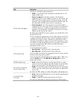
Page 792: ...access number and service node functions on Router B to meet the following requirements After the subscriber dials 300 the IVR access number from Telephone A Telephone B rings If the subscriber dials a wrong number at Telephone A Router B plays the audio file input_error wav If no number is dialed at Telephone A within the timeout time Router B plays the audio file timeout wav Figure 802 Network d...

Page 793: ...welcome for Description c Add two operations as shown in Figure 803 d Click Apply Configure an access number Select Voice Management IVR Services Access Number Management from the navigation tree and click Add to access the following page Figure 804 Configuring an access number ...

Page 794: ...bscriber dials 300 the IVR access number from Telephone A Router B plays the audio file bye wav and then terminates the call If the subscriber dials a wrong number at Telephone A Router B plays the audio file input_error wav If no number is dialed at Telephone A within the timeout time Router B plays the audio file timeout wav Figure 805 Network diagram Configuration procedure 1 Configure Router A...

Page 795: ...Node ID b Type reject call for Description c Add two operations as shown in Figure 806 d Click Apply Configure an access number Select Voice Management IVR Services Access Number Management from the navigation tree and click Add to access the following page ...

Page 796: ...nfigure an IVR access number and configure a call node jump node and service node on Router B to meet the following requirements After the subscriber dials 300 at Telephone A Router B plays the audio file welcome wav Then If the subscriber presses the key at Telephone A the call jumps to the service node and the subscriber hears voice prompts of the audio file bye wav After that the service node r...

Page 797: ... Media Resource c Click the Browse button of g729r8 codec to select the target file d Click Apply Use the same method to upload other g729r8 media resource files timeout input_error and bye Configure global error and timeout processing methods to achieve the following purposes If no number is dialed at Telephone A within the timeout time Router B plays audio file timeout wav If number of timeouts ...

Page 798: ... b Enter 4 for Max Count of Input Timeouts and 5 for Timeout Time select Enable for Play Voice Prompts for Input Timeout select timeout from the Voice Prompts list c Click Apply Configure a call node Select Voice Management IVR Services Advanced Settings from the navigation tree select the Configure Call Node tab and click Add to access the following page ...

Page 799: ...r play call for Description c Select Enable for Play Voice Prompts select Enable for Mandatory Play and select call from the Voice Prompts list d Enter 1 for Extension Number Enter 500 for Corresponding Number and click Add a Rule e Click Apply Configure a service node ...

Page 800: ... following page Figure 812 Configuring a service node a Enter 20 for Node ID b Enter reject call for Description c Add two operations as shown in Figure 812 d Click Apply Configure a jump node Select Voice Management IVR Services Advanced Settings from the navigation tree select the Configure Jump Node tab and click Add to access the following page ...

Page 801: ...4 Figure 813 Configuring a jump node a Enter 10 for Node ID b Enter play welcome for Description c Select Enable for both Play Voice Prompts and Mandatory Play d Select welcome from the Voice Prompts list ...

Page 802: ...t Telephone A Router B plays the audio file welcome wav Then the following events occur If you press the key at Telephone A the call jumps to service node 20 and you hear voice prompts of the audio file bye wav After that the service node releases the call If you press the key at Telephone A the call jumps to call node 10 and you hears the voice prompts of the audio file call wav After that if you...

Page 803: ...from the Menu Type list to access the following page Figure 815 Configuring a jump menu Table 291 Configuration items Item Description Menu Node ID Enter a menu ID Menu Name Enter a menu name Menu Type Select Jump By default Jump is selected Play Voice Prompts When the User Enters the Menu Select an audio file No audio file is selected by default ...

Page 804: ...evious node By default no method is set Specify A Menu Specify the target menu This setting is available when the Input Timeout Processing Method is Jump to a Menu Timeout Prompts Select an audio file No audio file is selected by default Key Mapping Map keys with operations which include Terminate the call Jump to a menu Return to the previous menu No key mapping is configured by default Jump to s...

Page 805: ...access the following page Figure 817 Entering the next menu Table 293 Configuration items Item Description Menu Node ID Enter a menu ID Menu Name Enter a menu name Menu Type Select Enter the next menu By default Jump is selected Play Voice Prompts When the User Enters the Menu Select an audio file No audio file is selected by default Jump to the next menu Select the target menu Configure a menu of...

Page 806: ...ted Play Voice Prompts When the User Enters the Menu Select an audio file No audio file is selected by default Configure a Dial immediately menu Select Dial immediately from the Menu Type list to access the following page Figure 819 Dial immediately menu Table 295 Configuration items Item Description Menu Node ID Enter a menu ID Menu Name Enter a menu name Menu Type Select Dial immediately By defa...

Page 807: ...ry call menu Select Secondary call from the Menu Type list to access the following page Figure 820 Secondary call menu Table 296 Configuration items Item Description Menu Node ID Enter a menu ID Menu Name Enter a menu name Menu Type Select Secondary call By default Jump is selected Play Voice Prompts When the User Enters the Menu Select an audio file No audio file is selected by default ...

Page 808: ...in the global key policy Specify A Menu Specify the target menu This setting is available when the Input Error Processing Method is Jump to a menu Timeout Prompts Select an audio file Voice prompt files can be configured in Voice Management IVR Services Media Resources Management Normal Secondary Call Number Matching Policy Select one of the following policies Match the terminator of the numbers M...

Page 809: ...ustomization from the navigation tree and click the icon of the target menu to access the Customize IVR Services page NOTE To perform any operation to the previous page you must close the Customize IVR Services page first Otherwise you will get errors Figure 822 Customizing IVR services Add a submenu Select Add A New Node from the Jump to submenu list of Key 0 Click OK on the popup dialog box to a...

Page 810: ... page click OK If you delete a menu that is referenced by another menu the operation deletes the reference relation in the menu but not the menu If you delete a menu that is referenced within itself the delete operation deletes both the reference relation and the menu Custom IVR service configuration example Network requirements Company A needs a custom IVR system to achieve the following purposes...

Page 811: ... the attendant If the user dials 1 the system plays the audio file that introduces product A If the user dials 2 the system plays the audio file that introduces product B If the user dials 3 the system plays the audio file that introduces product C If the user dials the system returns to the previous menu 4 Government production sales department This menu plays the audio file Welcome3 wav Then the...

Page 812: ...ly Use the same method to upload other g729r8 media resource files You can see these uploaded files in Voice Management IVR Services Media Resources Management as shown in Figure 825 Figure 825 Media file list 2 Configure the access number Configure the access number Select Voice Management IVR Services Access Number Management from the navigation tree and click Add to access the following page ...

Page 813: ...t Voice Management IVR Services Processing Methods Customization from the navigation tree and click Add to create a menu Figure 827 Configuring a menu a Enter 1 for Menu Node ID b Enter Voice Menu System of Company A for Menu Name c Select Jump from the Menu Type list and Hello from the Play Voice Prompts When the User Enters the Menu list d Click Next Bind the access number ...

Page 814: ...agement IVR Services Processing Methods Customization from the navigation tree to access the page shown in Figure 829 Click the icon of the menu to access the Customize IVR Services page shown in Figure 830 Figure 829 Menu list Figure 830 Customize IVR services Add submenus for the marketing and sales department telecom product sales department and government product sales department ...

Page 815: ...g box to access the following page Figure 832 Creating a submenu for the marketing and sales department a Enter 2 for Menu Node ID b Enter Marketing and Sales Dept for Menu Description c Select Jump from the Menu Type list and welcome1 from the Player Voice Prompts When the User Enters the Menu list d Click Apply Configure submenus for the telecom product department and government product departme...

Page 816: ...the government product sales department Return to the Customize IVR Service page Figure 835 Voice menu system of Company A a Select Terminate the call from the Operation list of key b Click Apply c Configure the marketing and sales department submenu Select Marketing and Sales Dept from the navigation tree ...

Page 817: ...he popup dialog box to access the following page Figure 837 Adding a submenu a Enter 8 for Menu Node ID b Enter Attendant for Menu Description c Select Dial immediately from the Menu Type list and type 500 for Call immediately d Click Apply Use the same method to add submenus for the major financial customer department carrier customer department and SMB department ...

Page 818: ...e configuration the marketing and sales department submenu is as shown in Figure 838 4 Configure the telecom product sales department submenu a Select Telecom Product Sales Dept from the navigation tree Figure 839 Telecom product sales department submenu a Select Jump from the Operation list and Attendant from the Jump to submenu list of key 0 ...

Page 819: ... Menu Type list and ProductA from the Play Voice Prompts When the User Enters the Menu list d Click Apply Use the same method to add submenus for introductions to Products B and C After that return to the Customize IVR Services page Figure 841 Telecom product sales department submenu a Select Return to the previous node from the Operation list of key b Click Apply After the configuration the telec...

Page 820: ...ubmenu as shown in Figure 842 The configuration procedure is identical with the configuration of the telecom product sales department submenu Figure 842 Government product sales department submenu After all the configuration the Customize IVR Services page is as shown in Figure 842 ...

Page 821: ...d Silent The calling party does not play any tones to the called party during call hold Playing music The calling party plays the specified tones to the called party during call hold By default the tone playing mode is the silent mode Media Resource Select the media resource if you select the Playing Music option You can upload media resource files in Voice Management IVR Services Media Resources ...

Page 822: ...ones DSCP Value in the ToS Field of the IP Packets Carrying RTP Stream Set the DSCP value in the ToS field in the IP packets that carry the RTP stream globally DSCP Value in the ToS Field of the IP Packets Carrying Voice Signaling Set the DSCP value in the ToS field in the IP packets that carry the voice signaling globally VPN Instance Specify a VPN instance for SIP on a PE By default no VPN insta...

Page 823: ...n batch Select Voice Management Advanced Configuration Batch Configuration from the navigation tree and then click the Create Numbers in Batch link in the Local Number area to access the page for creating numbers in batch as shown in Figure 845 Figure 845 Creating numbers in batch ...

Page 824: ...r registration and authentication Register Password Password used for registration and authentication FXS Lines Selected FXS Lines Available FXS Lines Select an FXS voice subscriber line in the Available FXS Lines box click to add the line into the Selected FXS Lines box Select an FXS voice subscriber line in the Selected FXS Lines box click to remove the line from the box Click to add all FXS voi...

Page 825: ...ansmit fax packets in the format of binary strings Enable Enable ECM Disable Disable ECM By default ECM is disabled To use ECM fax machines on both sides and the gateway must support ECM You must enable ECM mode for the local numbers and call routes corresponding to the fax sender and receiver in the ECM mode CNG Fax Switchover Function Enable CNG fax switchover function The CNG fax switchover is ...

Page 826: ... of the NTE payload type is 100 Select the Number s Select the checkboxes of specific local numbers and then click the Apply to Selected Number s button to apply the above fax and Modem settings to the selected local numbers Call services Select Voice Management Advanced Configuration Batch Configuration from the navigation tree and then click the Call Services link in the Local Number area to acc...

Page 827: ...default call hold is disabled After call hold is enabled set the Max Time Length the Held Party Can Wait parameter as needed IMPORTANT The Max Time Length the Held Party Can Wait is only applied to the held party of a call that is the receiver of call hold Call Transfer Configure call transfer Enable Disable By default call transfer is disabled Call hold must be enabled before you can configure ca...

Page 828: ...service is disabled Message Waiting Indicator Configure MWI Enable Disable By default MWI is disabled IMPORTANT Generally the voice gateway sends a SUBSCRIBE to the server and receives a NOTIFY from the server if the subscription is successful and gets the status of the voice mailbox afterwards Processing Priority When the Line is Busy Specify the processing sequence of services when the line is b...

Page 829: ...lephone event NTE transmission mode When you adopt this transmission mode you can configure the payload type field in RTP packets Number Sending Mode Specify number sending mode Send a Truncated Called Number Send All Digits of a Called Number Send Certain Number of Digits Send certain number of digits that are extracted from the end of a number of a called number The specified value should not be...

Page 830: ... active voice connection Speech signals are generated and transmitted only when an active voice segment is detected Researches show that VAD can save the transmission bandwidth by 50 Enable Disable By default VAD is disabled Select the Number s Select the boxes of desired local numbers and then click the Apply to Selected Number s button to apply the above advanced settings to the selected local n...

Page 831: ... correct errors and they transmit fax packets in the format of binary strings Enable Enable ECM for fax Disable Disable ECM for fax By default ECM fax is disabled ECM can work only if fax machines on both sides support ECM and the gateway is configured with ECM You must enable ECM mode for the local numbers and call routes corresponding to the fax sender and receiver in the ECM mode CNG Fax Switch...

Page 832: ...agement Advanced Configuration Batch Configuration from the navigation tree and then click the Advanced Settings link in the Call Route area to access the call route advanced settings page as shown in Figure 850 Figure 850 Call route advanced settings page Table 303 Configuration items Item Description Codecs and Priorities Codec with the First Priority Codec with the Second Priority Codec with th...

Page 833: ...an active voice segment is detected Researches show that VAD can save the transmission bandwidth by 50 Enable Disable By default VAD is disabled Select the Route s Select the boxes of desired call routes and then click the Apply to Selected Route s button to apply the above advanced settings to the selected call routes Line management FXS line configuration Select Voice Management Advanced Configu...

Page 834: ...ended to adjust the gain If necessary do it with the guidance of technical personnel Output Gain on the Voice Interface When a relatively small voice signal power is needed on the output line increases the voice output gain value DTMF Detection Sensitivity Level Set the DTMF detection sensitivity level Low In this mode the reliability is high but DTMF tones might fail to be detected Medium In this...

Page 835: ... second Input Gain on the Voice Interface When the voice signals on the line attenuate to a relatively great extent increases the voice input gain value IMPORTANT Gain adjustment might lead to call failures You are not recommended to adjust the gain If necessary do it with the guidance of technical personnel Output Gain on the Voice Interface When a relatively small voice signal power is needed on...

Page 836: ... expires before the dialing is completed the user will be prompted to hang up and the call is terminated Input Gain on the Voice Interface When the voice signals on the line attenuate to a relatively great extent increases the voice input gain value IMPORTANT Gain adjustment might lead to call failures You are not recommended to adjust the gain If necessary do it with the guidance of technical per...

Page 837: ...put Gain on the Voice Interface When a relatively small voice signal power is needed on the output line increases the voice output attenuation value Select the Line s Select the boxes of desired line and then click the Apply to Selected Line s button to apply the above settings to the selected ISDN lines SIP local survival services Select Voice Management Advanced Configuration Batch Configuration...

Page 838: ...bers from 2000 to 2004 Register User Quantity Specify the number of users to be registered Registration Mode Set the registration mode No username and password Username and password are the same as the number Username and password are specified uniformly If you select this option you must specify the authentication username and authentication password Authentication Username Enter the name of the ...

Page 839: ...vigation tree The Line State Information page appears Figure 856 Line state information page This page supports two types of voice subscriber lines Analog voice subscriber lines FXS FXO paging MoH and E M Digital voice subscriber lines BSV VE1 and VT1 Table 309 Field description Field Description Name Voice subscriber line name Type Voice subscriber line type BRI PRI FXS FXO EM PAGE MOH ISDN PRI I...

Page 840: ...e subscriber line is up both administratively and physically Displaying detailed information about analog voice subscriber lines For analog voice subscriber lines FXS FXO paging MoH and E M click the Details link to view details Figure 857 Paging line details Displaying detailed information about digital voice subscriber lines For digital voice subscriber lines BSV VE1 and VT1 click the Details li...

Page 841: ...link to view the details about the TS Figure 859 Timeslot details Call statistics The following pages display call statistics Active Call Summary page Displays statistics about ongoing calls History Call Summary page Displays statistics about ended calls ...

Page 842: ...Type Call type Only Speech and Fax are supported Status Call status Unknown The call status is unknown Connecting A connection attempt outgoing call is being made Connected A connection attempt incoming call is being made Active The call is active Displaying history call summary Select Voice Management States and Statistics Call Statistics from the navigation tree and click the History Call Summar...

Page 843: ...elect Voice Management Sates and Statistics SIP UA States from the navigation tree The TCP Connection Information page appears Figure 862 TCP connection information Table 311 Field description Field Description Connection ID Call connection ID automatically generated by the system Local Address IP address of the calling party Local Port Port number of the calling party Remote Address IP address of...

Page 844: ...cription Field Description Number Registered phone number Registrar Address of the registrar in the format of IP address plus port number or domain name Remaining Aging Time Sec Remaining aging time of a number that is the remaining time before the next registration Status Status of the number offline Not registered online Registered login Being registered logout Being deregistered dnsin DNS query...

Page 845: ...P address plus port number or domain name Remaining Aging Time Sec Remaining aging time of the subscription that is the remaining time before the next subscription Status Subscription status offline Not subscribed online Subscribed login The subscription is being proposed logout The subscription is being canceled Local survival service states Select Voice Management States and Statistics Local Sur...

Page 846: ...es Select Voice Management States and Statistics SIP Trunk Account States from the navigation tree The page for displaying SIP trunk account states appears Figure 867 SIP trunk account states Table 315 Field description Field Description Aging Time SIP trunk account aging time Status Registration status of the SIP trunk account Disabled Not in use Offline Not registered Online Registered Login Bei...

Page 847: ...ily saved on the device Called number of a forwarded call carried in a received 3xx message Destination number of a transferred call carried in a received REFER message Contact Address Real contact address of the number Remaining Aging Time Sec Remaining aging time of the contact address in seconds Type Type of the service that sets up the connection Register Registration of a roaming user Subscri...

Page 848: ...ys information about ongoing IVR playing Displaying IVR call states Select Voice Management States and Statistics IVR Information from the navigation tree The IVR Call States page appears Figure 870 IVR call states Table 317 Field description Field Description Corresponding Access Number IVR access number corresponding to the called number Current Menu Node Current menu node ID State Current state...

Page 849: ...formation from the navigation tree The IVR Play States page appears Figure 871 IVR play states Table 318 Field description Field Description Play Count Play times of the media file Play State Playing Not playing Play Type PSTN Called party is from PSTN IP IP address of the peer media ...

Page 850: ...series routers Model HP MSR900 MSR 900 MSR 900 W MSR 900 W NA MSR 920 MSR 920 W MSR 920 W NA HP MSR93X MSR930 JG51 1A MSR930 JG51 1B MSR930 JG512A MSR930 JG512B MSR930 JH012A MSR935 JH012B MSR930 JG513A MSR930 JG513B MSR930 JG596A MSR930 JG665A MSR931 JG514A MSR931 JG514B MSR931 JG515A MSR931 JG515B MSR931 JG531A MSR931 JG531B MSR933 JG516A MSR933 JG516B MSR933 JG517A MSR933 JG517B MSR935 JG518A M...

Page 851: ...SR 20 13 W NA HP MSR20 MSR 20 20 MSR 20 21 MSR 20 40 HP MSR30 MSR 30 10 MSR 30 1 1E MSR 30 1 1F MSR 30 16 MSR 30 20 MSR 30 40 MSR 30 60 MSR 30 10 DC MSR 30 20 DC MSR 30 40 DC MSR 30 60 DC MSR 30 16 PoE MSR 30 20 PoE MSR 30 40 PoE MSR 30 60 PoE HP MSR50 MSR 50 40 MSR 50 60 MSR 50 40 DC MSR 50 60 DC HP MSR1000 MSR1003 8 ...

Page 852: ...ing you will receive email notification of product enhancements new driver versions firmware updates and other product resources Related information Documents To find related documents browse to the Manuals page of the HP Business Support Center website http www hp com support manuals For related documentation navigate to the Networking section and select a networking category For a complete list ...

Page 853: ...eparated by vertical bars from which you select one choice multiple choices or none 1 n The argument or keyword and argument combination before the ampersand sign can be entered 1 to n times A line that starts with a pound sign is comments GUI conventions Convention Description Boldface Window names button names field names and menu items are in bold text For example the New User window appears cl...

Page 854: ... 2 features Represents an access controller a unified wired WLAN module or the switching engine on a unified wired WLAN switch Represents an access point Represents a security product such as a firewall a UTM or a load balancing or security card that is installed in a device Represents a security card such as a firewall card a load balancing card or a NetStream card Port numbering in examples The ...

Page 855: ...s wireless service detailed information 78 WLAN access wireless service AP radio binding 76 WLAN client mode configuration 102 105 WLAN client mode enabling 102 WLAN client mode statistics 104 WLAN RF ping information 84 access control configuration 152 153 user group configuration 282 access number configuration 760 accessing SSL VPN resources Web 428 ACL configuration 226 configuration guideline...

Page 856: ...SSL VPN 385 security for application protocols SSL VPN 385 simple deployment SSL VPN 385 algorithm STP calculation 299 alternate port MST 307 AP WLAN access wireless service AP radio binding 76 WLAN advanced settings configuration 132 WLAN wireless QoS WMM AP radio EDCA parameters 121 Appendix packet precedence 248 application configuring custom application 172 loading 171 application control conf...

Page 857: ... 162 BPDU STP BPDU forwarding 303 bride table interface list 272 MAC address list 272 bridge bridge table maintenance 272 enabling bridge set 276 277 filtering 274 forwarding 274 major functionality 272 MST common root bridge 307 307 MST regional root bridge 306 STP designated bridge 298 STP root bridge 297 VLAN transparency 276 bridging adding interface to bridge set 277 bridge set enabling 276 b...

Page 858: ...ckup 560 call barring 560 call forwarding 559 call hold 559 call transfer 560 call waiting 559 calling party control 561 CID on FXO voice line 562 CID on FXS voice line 561 configuration examples 567 configuring barge in 576 configuring call forwarding 562 568 configuring call hold 562 configuring call transfer 562 570 configuring call waiting 562 567 configuring silent monitor 576 configuring thr...

Page 859: ... configuration file backing up configuration Web 475 backing up device files through USB port Web 477 restoring configuration Web 476 restoring device files through USB port Web 477 restoring factory defaults Web 475 saving device configuration Web 474 configuration guideline PKI 473 static routing 183 configuration guidelines ACL 227 DHCP 204 IPsec VPN 361 RADIUS 332 configuration management back...

Page 860: ...e 557 fax and modem local number 554 fax and modem parameters for call routes 669 global key policy 753 gratuitous ARP 341 hunt group 571 IKE negotiation with RSA digital signature 467 immediate secondary call 775 internal hosts accessing public network 146 internal server 143 148 intrusion detection 162 IP network resources Web 398 IP routing 178 IP services DDNS 197 199 IP services DNS 189 IP se...

Page 861: ...r 673 SIP session properties 638 SIP session refresh 643 SIP signaling security 649 SIP source address binding 638 SIP trunk 662 664 673 SIP trunk account for registration 665 SIP voice mailbox server 648 SNMP community 256 SNMP group 257 SNMP trap function 260 SNMP user 258 SNMP view 254 SNMPv1 262 496 SNMPv2c 262 496 SNMPv3 266 498 source address binding 659 SSL VPN gateway Web 386 SSL VPN servi...

Page 862: ...gement 489 CPE performance monitoring 489 CPE status monitoring 489 CPE system software image management 489 network framework 488 D data WLAN RRM data transmit rates 1 1 1 WLAN RRM data transmit rates 802 1 1 1 1 1 WLAN RRM data transmit rates 802 1 1n MCS 1 12 data encryption PKI configuration 448 data link management 685 data link management E1 T1 685 685 686 687 687 DDNS 197 See also DNS confi...

Page 863: ...onfiguring VT1 line 693 discarding MST discarding port state 308 displaying 3G modem 134 3G wireless card state 27 active call summary 825 active route table 179 analog line state 823 broadband connection information 27 call statistics 824 client mode statistics 104 connection status 827 CRL 459 device information 26 digital line state 823 dynamic contact state 830 external interface traffic order...

Page 864: ...immediate start 703 wink start 703 E M subscriber line configuration 712 E M voice subscriber line 703 E1 E1 voice DSS1 signaling configuration 700 interface 686 E1 interface CE1 interface 686 ISDN PRI interface 686 E1 T1 fax function 687 feature 687 interface 686 introduction 685 PDH 685 protocol 687 signaling mode 687 standard 687 voice function 685 echo adjustment adjusting echo cancellation pa...

Page 865: ...eature call barring 560 call forwarding 559 call hold 559 call transfer 560 call waiting 559 E1 T1 687 hunt group 560 message waiting indication 560 SIP trunk 663 source address binding 659 three party conference 560 features fax function 687 protocol 687 signaling mode 687 standard 687 filtering configuring URL filtering 155 156 finishing configuration wizard 524 fixed ARP configuration 346 348 F...

Page 866: ...ing a tunnel 375 GRE IPv4 configuration 377 GRE IPv4 tunnel configuration 375 guest how WiNet guest administrator obtains guest password 513 H hardware 3G modem management 134 hello STP timer 304 help information about SSL VPN Web 429 HTTP managing services Web 479 HTTPS managing services Web 479 hunt group configuring 571 hunt group feature 560 I ICMP ping command 504 identity configuring SIP ide...

Page 867: ...uration 375 IPsec connection configuration 351 displaying VPN monitoring information 358 PKI configuration certificate management 448 VPN configuration 350 359 VPN configuration guidelines 361 IPv4 creating a GRE tunnel 375 GRE IPv4 configuration 377 GRE IPv4 tunnel configuration 375 static route creation 178 static routing configuration 180 WLAN QoS configuration 127 IPv6 WLAN QoS configuration 1...

Page 868: ...figuration 370 L2TP for VPN enabling 364 L3VPN VRF aware SIP 805 LAN user group configuration 282 LAN information displaying 28 Layer 3 DHCP client configuration 204 DHCP configuration 202 212 DHCP relay agent configuration 203 220 DHCP server configuration 203 traceroute 504 traceroute node failure identification 504 learning MST learning port state 308 limiting WLAN wireless QoS WMM rate 126 WLA...

Page 869: ...blacklist entry 161 mapping MSTP VLAN to instance mapping table 306 master port MST 307 max age timer STP 304 MCS WLAN RRM data transmit rates 802 1 1n MCS 1 12 media configuring SIP media security 641 message ARP configuration 338 ARP static configuration 341 gratuitous ARP configuration 341 IP services gratuitous ARP packet learning 338 IP services gratuitous ARP periodic packet send 346 securit...

Page 870: ...nnection limit 145 external network 140 internal network 140 private address 140 public address 140 network ARP static configuration 342 ARP static entry creation 339 configuring dynamic blacklist 1 15 configuring static blacklist 1 16 configuring white list WLAN security 1 17 gratuitous ARP 338 gratuitous ARP packet 338 IP services ARP entry removal 339 IP services DNS proxy configuration 190 IP ...

Page 871: ...onfiguration 377 IPsec VPN configuration 350 359 MSTP configuration 297 310 317 NMM SNMP configuration 251 494 packet filtering configuration 287 ping 504 QoS 235 244 RSTP configuration 297 security ARP attack protection configuration 346 SNMPv1 configuration 262 496 SNMPv2c configuration 262 496 SNMPv3 configuration 266 498 static route creation IPv4 178 static routing configuration IPv4 180 STP ...

Page 872: ...guration guidelines 473 configuring IKE negotiation with RSA digital signature 467 creating PKI domain 452 creating PKI entity 451 destroying RSA key pair 456 generating RSA key pair 455 requesting certificate from RSA Keon CA server 463 requesting certificate from Windows 2003 CA server 459 requesting local certificate 458 retrieving and displaying CRL 459 retrieving and displaying PKI certificat...

Page 873: ...ng 700 configuring exclusive IP addresses 210 configuring FXO voice subscriber line 709 719 configuring FXS voice subscriber line 706 configuring global advanced configuration 804 configuring gratuitous ARP 341 configuring IKE negotiation with RSA digital signature 467 configuring internal server 143 148 configuring intrusion detection 162 configuring IP network resources Web 398 configuring IP se...

Page 874: ...P application resources Web 391 configuring Telnet login control rule 335 configuring traffic ordrering 186 configuring trunking mode calling 548 configuring URL filtering 155 156 configuring user 283 configuring user access to SSL VPN Web 427 configuring user group 283 configuring user group Web 408 configuring user isolation 1 17 configuring user based load sharing Web 184 configuring VE1 line 6...

Page 875: ...ling echo cancellation nonlinear function 706 enabling IP services DNS proxy 190 enabling IP services dynamic ARP entry learning 340 enabling L2TP for VPN 364 enabling real time switching 665 enabling SIP trunk function 665 enabling SNMP agent 252 494 enabling WiNet 507 enabling WLAN client mode 102 enabling WLAN wireless QoS 1 19 entering configuration wizard homepage 522 finishing configuration ...

Page 876: ...unk configuration 664 voice function 685 public address NAT 140 Public Key Infrastructure Use PKI Q QoS ACL 226 adding IPv4 ACL 227 advanced limit 235 235 237 237 advanced queue 235 240 Appendix packet precedence 248 CBQ 235 240 configuration 127 configuring ACL rule Ethernet frame header 232 configuring advanced limit 237 configuring advanced queue 240 245 configuring bandwidth guarantee 241 conf...

Page 877: ...ar expression matching pattern 597 matching pattern metacharacter 597 relay agent DHCP configuration 203 Remote Authorization Dial In User Service Use RADIUS remote device pass through modem 553 removing IP services ARP entry 339 request SIP client 630 requesting local certificate 458 PKI certificate from RSA Keon CA server 463 PKI certificate from Windows 2003 CA server 459 resolving domain name ...

Page 878: ...347 blacklist 158 changing SSL VPN login password Web 429 configuring access control 152 153 configuring ACL rule Ethernet frame header 232 configuring application control 171 174 configuring attack protection 158 164 configuring authentication policies Web 414 configuring blacklist 160 configuring custom application application control 172 configuring IKE negotiation with RSA digital signature 46...

Page 879: ...e Web 432 connecting wireless service 103 door opening control 561 QoS 235 244 silent monitor 561 VCX support for SIP voice service 562 WLAN access service configuration 63 63 85 WLAN access service creation 63 WLAN access service security parameter dependencies 77 WLAN access service based VLAN configuration 87 WLAN access wireless service detailed information 78 WLAN access wireless service AP r...

Page 880: ...29 functions 629 629 local server operation mode configuration alive mode Web 737 local server operation mode configuration alone mode Web 734 local survival 728 local survival configuration 729 734 location server 629 629 message types 630 proxy server 628 redirect server 629 registrar 629 security 633 service configuration 729 SIP connection configuration 636 651 657 SIP server group management ...

Page 881: ...ion 251 494 source address configuring binding 659 source IP subnet limit QoS 235 236 source route bridging 272 source route translational bridging 272 specifying DNS server 191 traffic ordering mode 187 SRTP SIP media flow encryption 634 TLS SRTP combination 635 SSH managing services Web 479 SSL accessing SSL VPN resources Web 428 configuring SSL VPN gateway Web 386 configuring SSL VPN service We...

Page 882: ... SVP WLAN wireless QoS WMM service set 1 19 switching to management level Web 483 synchronizing user group configuration for wan interface 289 syslog configuration Web 500 display Web 500 setting log host Web 501 setting syslog buffer capacity Web 502 setting syslog refresh interval Web 502 system managing the system Web 474 system administration application control configuration 285 bandwidth con...

Page 883: ... protocol packets 297 TR 069 auto connection between ACS and CPE 488 auto configuration 488 basic functions 488 configuration Web 487 CPE configuration file management 489 CPE performance monitoring 489 CPE status monitoring 489 CPE system software image management 489 network framework 488 traceroute IP address retrieval 504 504 node failure detection 504 504 system maintenance 504 traffic ACL 22...

Page 884: ...acklist entry 162 user information Web 410 virtual private dialup network Use VPDN VLAN bridging 276 DHCP client configuration 204 DHCP configuration 202 DHCP relay agent configuration 203 DHCP server configuration 203 MSTP VLAN to instance mapping table 306 WLAN advanced settings configuration 132 voice binding access number 791 call node configuration 754 779 configuration wizard 522 configuring...

Page 885: ...nt 816 call authority control configuration 733 739 call route 525 call route configuration 528 531 call rule set configuration 733 call service 525 559 call service configuration call route 566 call service configuration local number 562 call statistics displaying 824 call out route configuration 731 configuring BSV line 695 configuring coding parameters call route 589 configuring coding paramete...

Page 886: ...rect calling configuration static address 531 FoIP 552 local number 525 local number configuration 527 531 proxy server involved calling configuration 541 trunking mode calling configuration 548 VPDN L2TP 363 LAC 363 LNS 363 VPN accessing SSL VPN resources Web 428 adding L2TP group 364 changing SSL VPN login password Web 429 client initiated VPN configuration 370 configuring IKE negotiation with R...

Page 887: ...tication policies 414 configuring IP network resources 398 configuring local user 405 configuring resource group 403 configuring SSL VPN gateway 386 configuring SSL VPN service 387 432 configuring system time 484 configuring TCP application resources 391 configuring TR 069 487 configuring user access to SSL VPN 427 configuring user group 408 configuring Web management 474 configuring Web proxy ser...

Page 888: ... guest administrator obtains guest password 513 managing 509 RADIUS authentication configuration 518 roles 507 setting WiNet topology background image 508 wireless QoS configuration 1 19 1 19 enable 1 19 WMM 120 WMM AP radio EDCA parameters 121 WMM CAC service configuration 127 WMM client EDCA parameters 122 WMM client statistics display 125 WMM radio statistics display 123 WMM rate limiting 126 W...

Page 889: ...lacklist 1 15 configuring static blacklist 1 16 configuring user isolation 1 17 configuring white list 1 17 configuring white list functions 1 15 white list 1 15 WMM WLAN wireless QoS AP radio EDCA parameters 121 WLAN wireless QoS CAC admission policy 120 WLAN wireless QoS CAC service configuration 127 WLAN wireless QoS client EDCA parameters 122 WLAN wireless QoS client statistics display 125 WLA...

Reviews: