background image


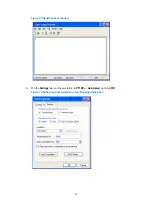
Figure 23


HyperTerminal window 


6.


On the 

Settings

 tab, set the emulation to 

VT100

 or 

Auto detect

 and click 

OK

Figure 24


Setting terminal emulation in test Properties dialog box


21 

Summary of Contents for MSR1002-4

Page 1: ...HP MSR1000 Routers Installation Guide Part number 5998 7749 Document version 6W102 20150814 ...

Page 2: ...ATERIAL INCLUDING BUT NOT LIMITED TO THE IMPLIED WARRANTIES OF MERCHANTABILITY AND FITNESS FOR A PARTICULAR PURPOSE Hewlett Packard shall not be liable for errors contained herein or for incidental or consequential damages in connection with the furnishing performance or use of this material The only warranties for HP products and services are set forth in the express warranty statements accompany...

Page 3: ... the rack 12 Grounding the router with a grounding strip 14 15 Grounding the router with a grounding conductor buried in the earth ground 15 Installing an interface module Installing a SIC 15 Installing a DSIC 16 17 Connecting interface cables 18 Attaching a USB device 18 Logging in through the console port 18 Connecting a console cable 19 Setting terminal parameters Connecting an AC power cord 22...

Page 4: ...e guidelines 30 Appendix A Chassis views and technical specifications 31 Chassis views 31 MSR1002 4 31 MSR1003 8 32 MSR1003 8S 32 Technical specifications 33 Appendix B LEDs 34 Panel LEDs 34 LED description 35 Appendix C Slot arrangement 36 Support and other resources 37 Contacting HP 37 Subscription service 37 Related information 37 Documents 37 Websites 37 Conventions 38 Index 40 ...

Page 5: ... an alert that calls attention to important information that if not understood or followed can result in personal injury CAUTION means an alert that calls attention to important information that if not understood or followed can result in data loss data corruption or damage to hardware or software General safety recommendations Keep the chassis and installation tools away from walk areas Make sure...

Page 6: ...SD and introduce problems such as loose captive screws and circuit failure High temperature can accelerate the aging of insulation materials and significantly lower the reliability and lifespan of the switch Table 2 Temperature and humidity requirements Temperature Humidity 0 C to 45 C 32 F to 113 F 5 to 90 noncondensing Cleanliness Dust buildup on the chassis might result in electrostatic adsorpt...

Page 7: ... the ESD wrist strap for safety Make sure the resistance reading is in the range of 1 to 10 megohm Mohm between human body and the ground To prevent electrostatic discharge ESD follow these guidelines Make sure the router and the floor are reliably grounded Take dust proof measures for the equipment room Maintain the humidity and temperature at a compliant level Always wear an ESD wrist strap and ...

Page 8: ...omagnetic shielding for example shielded interface cables when necessary Lightning protection To better protect the MSR1000 router from lightning perform the following tasks Make sure the grounding cable of the chassis is reliably grounded Make sure the grounding terminal of the AC power receptacle is reliably grounded Install a lightning arrester at the input end of the power supply to enhance th...

Page 9: ...ntration 3 104 particles m3 No visible dust on desk within three days Cleanness The equipment and floor are reliably grounded The equipment room is dust proof The humidity and temperature are at a compliant level Installation site Wear an ESD wrist strap and uniform when touching a circuit board ESD prevention Place the removed interface module on an antistatic workbench with the face upward or pu...

Page 10: ...supply UPS The emergency power switch in the equipme room is located Workbench The workbench is stable enough The workbench is reliably grounded Rack mounting requirements uter st 0 8 m The rack has a good ventilation system The rack is sturdy enough to support the weight of the router and installation accessories The size of the rack is appropriate for the ro The front and rear of the rack are at...

Page 11: ...eal on a mounting screw on the chassis cover intact and if you want to open the chassis contact HP for permission Otherwise HP shall not be liable for any consequence Installation prerequisites You have read Preparing for installation carefully All requirements in Preparing for installation are met Installation flowchart You can install the router on a workbench or on a rack Select an installation...

Page 12: ...onnect the router to a configuration terminal Connect the power cord Verify the installation Power on the router Troubleshoot the router Power off the router Operating correctly End Mount the router on a workbench Mount the router in a rack Determine the installation position Workbench mounting Rack mounting 8 ...

Page 13: ... grounded 2 Place the router upside down on the workbench and attach the rubber feet to the four round holes in the chassis bottom Figure 3 Attaching the rubber feet 3 Place the router on the workbench with the upside up Figure 4 Mounting the router on a workbench Installing the router in a rack WARNING The mounting brackets can only support the weight of the router To avoid damage to the router d...

Page 14: ...e same level Figure 5 Marking the positions of cage nuts 2 Insert one edge of a cage nut into the hole Use a flat blade screwdriver to compress the other edge of the cage nut and then push the cage nut fully into the hole 3 Repeat step 3 to install other cage nuts to all the marked positions on the front rack posts Figure 6 Installing cage nuts 10 ...

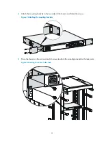
Page 15: ...the two sides of the chassis and fasten the screws Figure 7 Attaching the mounting brackets 5 Place the chassis on the rack and use M6 screws to attach the mounting brackets to the rack posts Figure 8 Securing the router to the rack 11 ...

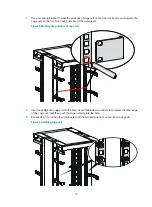
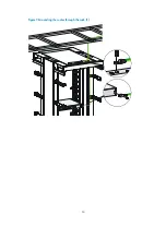
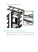
Page 16: ...ack is reliably grounded before grounding the router To connect the grounding cable 1 Remove the grounding screw from the grounding hole at the rear of the chassis 2 Use the grounding screw to attach the ring terminal of the grounding cable to the chassis See Figure 9 3 Remove the hex nut from a grounding post on the rack s grounding bar 4 Use needle nose pliers to bend a hook at the other end of ...

Page 17: ...Figure 9 Grounding the router through the rack 1 13 ...

Page 18: ...Grounding the router with a grounding strip If a grounding strip is available at the installation site connect the grounding cable to the grounding strip Follow the same procedures in Grounding the router through the rack to connect the grounding cable 14 ...

Page 19: ...ng cable to the angel iron or steel tube and treat the joint for corrosion protection Installing an interface module Installing a SIC CAUTION SICs are not hot swappable Make sure the router is powered off before installing a SIC To install a SIC 1 Remove the fastening screws on the filler panel with a Phillips screwdriver and remove the filler panel Keep the removed filler panel for future use 2 P...

Page 20: ...off before installing a DSIC The MSR1002 4 router does not support DSICs To install a DSIC 1 Remove the screws on the filler panel on slot 1 and slot 2 of the router to remove the filler panel as shown in Figure 14 Figure 15 2 Loosen the captive screws on the slot divider and pull out the slot divider as shown in Figure 14 Removing the filler panel 16 ...

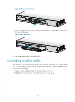
Page 21: ... secure the DSIC Connecting interface cables Connect interface cables before powering on the router This section describes how to connect Ethernet cables For other cable connection methods see HP MSR Series Routers Interface Module User Guide To connect an Ethernet cable 1 Plug one end of an Ethernet cable into the Ethernet port on the router 2 Plug the other end of the cable into the Ethernet por...

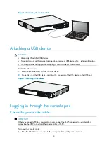
Page 22: ...move the protective cap from the USB device 2 Correctly orient the USB device and plug the connector of the USB device to the USB port Figure 18 Attaching a USB device Logging in through the console port Connecting a console cable IMPORTANT When you connect a PC to a powered on router connect the RJ 45 connector to the router after connecting the DB 9 connector of the console cable to the PC To co...

Page 23: ...l parameters This section uses a PC with Windows XP as an example To set terminal parameters 1 Select Start All Programs Accessories Communications HyperTerminal The Connection Description dialog box appears Figure 20 Connection description 2 Select the serial port to be used from the Connect using list and click OK 19 ...

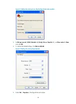
Page 24: ... 3 Set Bits per second to 9600 Data bits to 8 Parity to None Stop bits to 1 and Flow control to None and click OK 4 To restore the default settings click Restore Defaults Figure 22 Setting the serial port parameters 5 Select File Properties in the HyperTerminal window 20 ...

Page 25: ...Figure 23 HyperTerminal window 6 On the Settings tab set the emulation to VT100 or Auto detect and click OK Figure 24 Setting terminal emulation in test Properties dialog box 21 ...

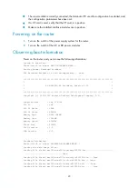
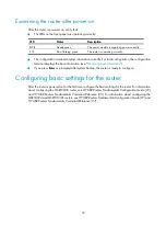
Page 26: ...Verifying the installation After you complete the installation verify that There is enough space for heat dissipation around the router and the rack or workbench is stable Interface modules are correctly installed The router rack and power cord are reliably grounded The correct power source is used Powering on the router Verifying before power on Before powering on the router verify the following ...

Page 27: ...Booting Normal Extended BootWare The Extended BootWare is self decompressing Done HP MSR1003 8S BootWare Version 2 30 Copyright c 2010 2015 Hewlett Packard Development Company L P Compiled Date Sep 11 2014 CPU ID 0x8 CPU L1 Cache 32KB CPU L2 Cache 256KB Memory Type DDR3 SDRAM Memory Size 1024MB Memory Speed 400MHz Flash Size 256MB CPLD Version 1 0 PCB Version 2 0 BootWare Validating Press Ctrl B t...

Page 28: ...t for DSA signature verification passed Known answer test for random number generator passed Known Answer tests in the user space passed Starting Known Answer tests in the kernel Known answer test for SHA1 passed Known answer test for HMAC SHA1 passed Known answer test for AES passed Known answer test for random number generator passed Known Answer tests in the kernel passed Starting Known Answer ...

Page 29: ... information see Observing boot information If you press Enter as prompted after system bootup the router is ready to configure Configuring basic settings for the router After the router is powered on for the first time configure the basic settings for the router For information about configuring the MSR1003 8 router see HP MSR Routers Fundamentals Configuration Guide V5 and HP MSR Routers Fundame...

Page 30: ...slide rails 3 Install a new SIC For the installation procedure see Installing the router If you do not install a SIC install a filler panel and tighten the screws Figure 26 Removing a SIC Figure 27 Installing a filler panel Replacing a DSIC 1 Loosen the captive screws on the DSIC 2 Gently pull the DSIC out along the slide rails If you need to install a DSIC or SICs see Installing the router for th...

Page 31: ...nd 4 3 Gently push the slot divider into the DSIC slot along the slide rails and tighten the screws 4 Install the filler panels and tighten the screws Figure 28 Removing a DSIC Figure 29 Installing the slot divider Figure 30 Installing filler panels ...

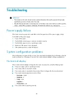
Page 32: ... power source is operating correctly 4 Determine if the power cord is damaged 5 If the problem persists contact HP Support System configuration problems If the configuration environment setup is correct the console terminal displays boot information when the router is powered on If the setup is incorrect the console terminal displays nothing or garbled text No terminal display If the console termi...

Page 33: ...han 4 seconds to reboot the router and restore the factory settings Then you can use the username and password shipped with the router to log in to the router When the router configuration must be saved and you have a console cable you can log in to the router from the BootWare menu Scenario 2 Symptom After the configuration is modified the network connectivity is lost When you check the configura...

Page 34: ...s the Reset button You can use the button to reboot the system or restore the factory settings 1 Press the Reset button for a short time to reboot the router 2 Press the Reset button for more than 4 seconds to reboot the router and restore the factory settings ...

Page 35: ... MSR1002 4 Figure 31 Front view 1 Power receptacle 2 Gigabit Ethernet port GE0 3 Gigabit Ethernet ports GE1 to GE4 4 SFP port SFP5 5 Asynchronous synchronous serial interface SERIAL0 6 Console port AUX port CON AUX 7 Reset button RESET 8 USB port Figure 32 Rear view 1 SIC slot 2 2 SIC slot 1 3 Grounding terminal 31 ...

Page 36: ... Reset button RESET 6 USB port 7 Gigabit Ethernet port GE0 Figure 34 Rear view 1 SIC slot 3 2 SIC slot 2 3 SIC slot 1 4 Grounding terminal MSR1003 8S Figure 35 Front view 1 Power receptacle 2 Gigabit Ethernet port GE1 3 Gigabit Ethernet ports GE2 to GE8 4 Console port AUX port CON AUX 5 Reset button RESET 6 USB port 7 Gigabit Ethernet port GE0 32 ...

Page 37: ... 3 SIC slots 1 DSIC slot 3 SIC slots 1 DSIC slot Dimensions H W D 44 2 360 300 mm 1 74 14 17 11 81 in 44 2 360 300 mm 1 74 14 17 11 81 in 44 2 360 300 mm 1 74 14 17 11 81 in excluding rubber feet and mounting brackets Rated voltage range 90 VAC to 264 VAC 50 Hz 60 Hz Rated voltage range 90 VAC to 264 VAC 50 Hz 60 Hz Rated voltage range 90 VAC to 264 VAC 50 Hz 60 Hz AC power supply Rated power for ...

Page 38: ...R 4 System status LED SYS 5 10 100 Mbps link LED for the Gigabit Ethernet port 6 1000 Mbps link LED for the Gigabit Ethernet port Figure 38 MSR1003 8 LEDs 1 System LED SYS 2 Power supply LED PWR 3 Gigabit Ethernet port LEDs GE0 to GE9 Figure 39 MSR1003 8S LEDs 1 System LED SYS 2 Power supply LED PWR 3 Gigabit Ethernet port LEDs GE0 to GE9 5 6 2 5 6 1 34 ...

Page 39: ...ower input SERIAL0 Steady green A link is present Flashing green Data is being received or transmitted Off No link is present GE 1000 Mbps link LED Steady green A 1000 Mbps link is present Flashing green Data is being received or transmitted at 1000 Mbps Off No 1000 Mbps link is present 10 100 Mbps link LED Steady yellow A 10 100 Mbps link is present Flashing yellow Data is being received or trans...

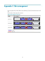
Page 40: ...s for SICs A DSIC can be installed if you remove the slot divider between two SIC slots The slot number of fixed ports on the router is 0 Table 6 Slot arrangement on the router Router Slot arrangement MSR1002 4 MSR1003 8 MSR1003 8S SIC slot DSIC slot 36 ...

Page 41: ...you will receive email notification of product enhancements new driver versions firmware updates and other product resources Related information Documents To find related documents browse to the Manuals page of the HP Business Support Center website http www hp com support manuals For related documentation navigate to the Networking section and select a networking category For a complete list of a...

Page 42: ... by vertical bars from which you select one choice multiple choices or none x y The argument or keyword and argument combination before the ampersand sign can be entered 1 to n times 1 n A line that starts with a pound sign is comments GUI conventions Convention Description Window names button names field names and menu items are in bold text For example the New User window appears click OK Boldfa...

Page 43: ... a unified wired WLAN module or the switching engine on a unified wired WLAN switch Represents an access point Represents a mesh access point Represents omnidirectional signals Represents directional signals Represents a security product such as a firewall UTM multiservice security gateway or load balancing device Represents a security card such as a firewall load balancing NetStream SSL VPN IPS o...

Page 44: ...rd XE connecting AC power cord XE procedure connecting AC power cord XE power supply connecting power cord XE power cord connecting AC XE AC connecting power cord 1 Grounding the router through the rack XE hardware grounding router through rack XE electrical grounding router through rack XE procedure grounding router through rack XE grounding rack 22 Connecting interface cables XE connecting route...

Page 45: ...pply failure XE procedure troubleshooting power supply failure 9 Installing the router XE installing router XE procedure installing the router XE hardware router installation XE network management router installation 28 Powering on the router XE powering on router XE electrical powering on the router XE procedure powering on the router 9 22 L Powering on the router XE powering on router XE electri...

Page 46: ... 28 T Technical specifications XE technical specifications CON AUX port XE technical specifications USB console port XE technical specifications USB port XE technical specifications Gigabit Ethernet port XE technical specifications SIC DSIC slot XE technical specifications memory XE technical specifications CF card memory XE technical specifications CF card slot XE technical specifications chassis...

Reviews: