256
Figure 98
Network diagram
Configuration procedure
1.
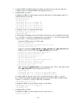
Configure the IPv6 addresses for all VLAN interfaces. (Details not shown.)
2.
Configure IPv6 static routes:
# Enable IPv6 and configure a default IPv6 static route on Switch A.
<SwitchA> system-view
[SwitchA] ipv6
[SwitchA] ipv6 route-static :: 0 4::2
# Enable IPv6 and configure two IPv6 static routes on Switch B.
<SwitchB> system-view
[SwitchB] ipv6
[SwitchB] ipv6 route-static 1:: 64 4::1
[SwitchB] ipv6 route-static 3:: 64 5::1
# Enable IPv6 and configure a default IPv6 static route on Switch C.
<SwitchC> system-view
[SwitchC] ipv6
[SwitchC] ipv6 route-static :: 0 5::2
3.
Configure the IPv6 addresses for all the hosts based on the network diagram, configure the default
gateway of Host A, Host B, and Host C as 1::1, 2::1, and 3::1.
4.
Verify the configuration:
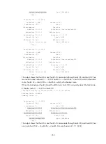
# Display the IPv6 routing table on Switch A.
[SwitchA] display ipv6 routing-table
Routing Table :
Destinations : 5 Routes : 5
Destination : :: Protocol : Static
NextHop : 4::2 Preference : 60
Interface : Vlan200 Cost : 0
Destination : ::1/128 Protocol : Direct
NextHop : ::1 Preference : 0
Interface : InLoop0 Cost : 0


