320
Source IP: FE80::20F:FF:FE00:1202 (link-local address of VLAN-interface 10 on
Switch A)
Destination IP: FE80::20F:FF:FE00:1200 (link-local address of VLAN-interface 10 on
Switch B)
Session State: Up Interface: Vlan10
Hold Time: /
# Display routes destined for 2001:4::0/64 on Switch A.
<SwitchA> display ipv6 routing-table 2001:4::0 64 verbose
Routing Table :
Summary Count : 1
Destination : 2001:4::0 PrefixLength : 64
NextHop : 2001::2 Preference : 15
IpPrecedence : QosLcId :
RelayNextHop : :: Tag : 0H
Neighbor : :: ProcessID : 0
Interface : Vlan-interface10 Protocol : ISISv6
State : Active Adv Cost : 20
Tunnel ID : 0x0 Label : NULL
Age : 4538sec
The output shows that Switch A and Switch B communicate through VLAN-interface 10.
When the link over VLAN-interface 10 fails, BFD can quickly detect the failure.
# Display the BFD information on Switch A.
<SwitchA> display bfd session
Switch A has deleted the BFD session on VLAN-interface 10 to Switch B and displays no output.
# Display routes destined for 2001:4::0/64 on Switch A.
<SwitchA> display ipv6 routing-table 2001:4::0 64 verbose
Routing Table :
Summary Count : 1
Destination : 2001:4::0 PrefixLength : 64
NextHop : 2001:2::2 Preference : 15
IpPrecedence : QosLcId :
RelayNextHop : :: Tag : 0H
Neighbor : :: ProcessID : 0
Interface : Vlan-interface11 Protocol : ISISv6
State : Active Adv Cost : 30
Tunnel ID : 0x0 Label : NULL
Age : 4610sec
The output shows that Switch A and Switch B communicate through VLAN-interface 11.
IPv6 IS-IS MTR configuration example
Network requirements
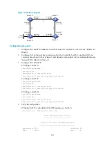
As shown in
, enable IPv6 IS-IS MTR to make the switches perform route calculation separately
in IPv4 and IPv6 topologies.


