background image


19 

4G extender cables from other vendors, for any consequences resulting from which HP assumes no 

liabilities. 

Table 6


HP 4G extender cables 

J number 

HP 4G extender cable

JG522A 

HP MSR 2.8m Extender Cable 

JG666A 

HP MSR 6m Extender Cable 

JG667A 

HP MSR 15m Extender Cable 


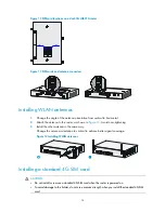
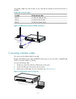
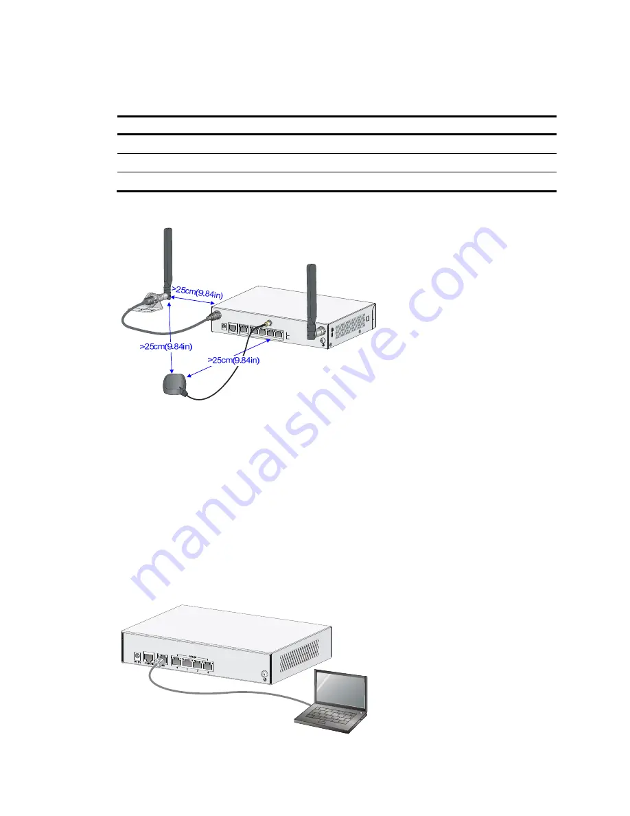
Figure 22


JG704A router antenna installation precautions 


Connecting interface cables 

This section uses the Ethernet cable for example. 
Because fixed Ethernet ports support MDI/MDIX autosensing, you can use either a straight-through 

cable or a crossover cable for connection. 
To connect an Ethernet cable: 

1.


Connect one end of the cable to an Ethernet port on the router. 

2.


Connect the other end of the cable to the peer device. 

3.


Examine the port LED status. For more information, see "

LED description

." 

Figure 23


Connecting the router to a computer 


Summary of Contents for MSR93x Series

Page 1: ...HP MSR93X Routers Installation Guide Part number 5998 3616a Document version 6W102 20141219 ...

Page 2: ...MATERIAL INCLUDING BUT NOT LIMITED TO THE IMPLIED WARRANTIES OF MERCHANTABILITY AND FITNESS FOR A PARTICULAR PURPOSE Hewlett Packard shall not be liable for errors contained herein or for incidental or consequential damages in connection with the furnishing performance or use of this material The only warranties for HP products and services are set forth in the express warranty statements accompan...

Page 3: ...4G antenna extender cable to a 4G device 17 Installing a GPS antenna 18 JG704A router antenna installation instructions 18 Connecting interface cables 19 Connecting the console cable and setting terminal parameters 20 Setting console terminal parameters 20 Connecting the power adapter 23 Verifying the installation 24 Powering on the router 24 Startup process 24 Power on check 25 Configuring basic ...

Page 4: ...13A 36 JG514A 37 JH009A 37 JG515A 38 JG531A 39 JG516A 39 JH010A 40 JG517A 41 JG518A 41 JH011A 42 JG519A 43 JH013A 43 JG520A 44 JG596A 45 JG665A 45 JG704A 46 JG597A 47 Technical specifications 47 Antenna specifications 49 Appendix B LEDs 51 LEDs 51 JG511A 51 JG512A 51 JH012A 52 JG513A 53 JG514A 53 JH009A 54 JG515A 55 JG531A 55 JG516A 56 JH010A 57 JG517A 57 JG518A 58 JH011A 59 JG519A 59 JH013A 60 JG...

Page 5: ...iii LED description 64 Index 67 ...

Page 6: ...ter TI BJNGA BB0023 JG519A HP MSR935 Wireless Router BJNGA BB0024 JH013A HP MSR935 Wireless Router NA BJNGA BB0024 JG520A HP MSR935 3G Router BJNGA BB0025 JG596A HP MSR930 4G LTE 3G CDMA Router BJNGA BB0026 JG665A HP MSR930 4G LTE 3G WCDMA Router BJNGA BB0027 JG704A HP MSR930 4G LTE 3G WCDMA ATT Router BJNGA BB0033 JG597A HP MSR936 Wireless Router BJNGA BB0028 Safety recommendations WARNING Before...

Page 7: ...t productdata iteconetworking html Site requirements The router can only be used indoors This section provides information about temperature humidity cleanness and air quality requirements as well as rack mounting requirements and protection against damage from lightning and EMI Table 2 Temperature and humidity requirements Temperature Relative humidity 0 C to 40 C 32 F to 104 F 5 to 90 Table 3 Du...

Page 8: ... reading should be in the range of 1 to 10 megohm Mohm between human body and the ground EMI EMI from any source adversely affects the router To prevent EMI Use electromagnetic shielding when necessary Take measures against interference from the power grid Position the router as far as possible from any power source s grounding equipment or light prevention equipment Position the router as far as ...

Page 9: ...densing Cleanness Dust concentration 3 104 particles m3 ESD prevention The equipment and floor are correctly grounded The equipment room is dust controlled Humidity and temperature are maintained at acceptable levels Wear an ESD wrist strap when inspecting or handling a circuit board EMI prevention Take measures to protect the power system from the power grid system Keep the protection ground of t...

Page 10: ...al Electricity safety Install a UPS In case of emergency during operation switch off the external power switch Workbench The workbench is stable The workbench is grounded correctly Safety precautions The router is far away from any sources of heat or moisture The emergency power switch in the equipment room is identified and accessible Installation accessories and tools Installation accessories su...

Page 11: ...l on a mounting screw on the chassis cover intact and if you want to open the chassis contact HP for permission Otherwise HP shall not be liable for any consequence Installation prerequisites You have read Preparing for installation carefully All requirements in Preparing for installation are met Installation flowchart You can install the router on a workbench or on a wall Select an installation m...

Page 12: ...correctly grounded 2 Place the router upside down on the workbench and attach the rubber feet to the four round holes in the chassis bottom Install the router on a wall Yes No Start Install the router Install wall mounting screws Ground the router Install antennas Connect interface cables Connect the router to a console terminal Connect the power adapter Verify the installation Power on the router...

Page 13: ...lows Router model Separation JG511A JG512A JH012A JG513A JG596A JG665A and JG704A 180 mm 7 09 in JG514A JH009A JG515A JG531A JG516A JH010A JG517A JG518A JH011A JG519A JH013A JG520A and JG597A 240 mm 9 45 in The holes must be level on the same horizontal line 2 Drill two holes in the wall 3 Following the marks drill the two holes at least 22 mm 0 87 in deep Verify that the holes are level 4 Insert ...

Page 14: ...esistance is less than 5 ohms You can ground the router with a grounding strip or to a buried grounding conductor Grounding the router with a grounding strip 1 Remove the grounding screw from the router chassis 2 Put the ring terminal of the grounding cable on the grounding screw 3 Use a screwdriver to fasten the grounding screw 4 Attach the other end of the grounding cable to the grounding strip ...

Page 15: ...ing conductor as shown in Figure 6 Figure 6 Grounding to a conductor buried in the earth Installing a standard 3G SIM card CAUTION Do not install or remove a standard 3G SIM card when the router is powered on To avoid damage to the holder do not use excessive strength when you install the standard 3G SIM card The HP MSR93X routers support the following frequency ranges 3G 800 850 900 1900 2100 MHz...

Page 16: ...r in the direction marked OPEN so the holder projects upwards Do not directly insert the standard 3G SIM card into the holder or lift the holder Figure 8 illustrates the wrong installation methods Figure 8 Wrong installation methods 3 Insert the standard 3G SIM card along the slide rails to the holder 4 Put down the holder and push the holder in the direction marked LOCK to lock the card in positi...

Page 17: ...G antenna To install a 3G antenna 1 Thread the male connector of the 3G cable through the hole on the bracket and use screws from behind the bracket to secure the male connector to the bracket 2 Change the angle of the antenna orientation from vertical to horizontal 3 Attach the antenna to the male connector of the cable 4 Attach the female connector of the cable to the router ...

Page 18: ... the 3G extender cable if the router has antennas installed Ensure a minimum of 25 cm 9 84 in distance between the 3G antenna when the extender cable is used and the chassis and between the 3G antenna and any other antenna installed on or connected to the router Table 5 lists HP extender cables You can use HP extender cables but HP is not liable for any consequences caused thereby Table 5 3G exten...

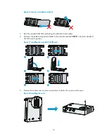
Page 19: ... router as shown in Figure 14 Avoid over tightening 3 Install the other antenna in the same way Change the antenna orientation to vertical to achieve better signal coverage Figure 14 Installing WLAN antennas Installing a standard 4G SIM card CAUTION Do not install or remove a standard 4G SIM card when the router is powered on To avoid damage to the holder do not use excessive strength when you ins...

Page 20: ...0 900 1800 2100 2600 MHz LTE 3G 900 2100 MHz WCDMA HSDPA HSUPA HSPA 2G 900 1800 1900 MHz GSM GPRS EDGE To install a standard 4G SIM card 1 Use a screwdriver to loosen the screws on the standard 4G SIM card socket cover on the bottom of the chassis and remove the cover Figure 15 Removing the 4G SIM card socket cover 2 Push the 4G SIM card holder in the direction marked OPEN so the holder projects u...

Page 21: ...rails to the holder 4 Put down the holder and push the holder in the direction marked LOCK to lock the standard 4G SIM card in position Figure 17 Installing the standard 4G SIM card 5 Position the socket cover and use a screwdriver to fasten the screws on the cover Figure 18 Installing the cover ...

Page 22: ...Installing a 3G 4G antenna extender cable to a 4G device One 3G 4G antenna extender cable is provided with the JG704A router No 3G 4G antenna extender cable is provided with other router models Purchase 3G 4G antenna extender cables as required To install a 3G 4G antenna extender cable to a 4G device 1 Thread the male connector of the cable through the hole on the bracket and use screws from behin...

Page 23: ... antenna installation instructions When you install a 4G or GPS antenna to a JG704A router follow these guidelines Ensure a minimum distance of 25 cm 9 84 in between the antenna and any other antenna on the router Ensure a minimum distance of 25 cm 9 84 in between the GPS antenna or the 4G antenna when an extender cable is used and the router Only one 4G extender cable is provided with the router ...

Page 24: ...stallation precautions Connecting interface cables This section uses the Ethernet cable for example Because fixed Ethernet ports support MDI MDIX autosensing you can use either a straight through cable or a crossover cable for connection To connect an Ethernet cable 1 Connect one end of the cable to an Ethernet port on the router 2 Connect the other end of the cable to the peer device 3 Examine th...

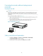
Page 25: ... Figure 24 1 Select a console terminal which can be an ASCII terminal with an RS232 serial port or a PC A PC is more commonly used 2 Connect the DB 9 connector female of the console cable to the RS 232 serial port of the console terminal and the RJ 45 connector to the console port of the router Figure 24 Connecting the console cable Setting console terminal parameters 1 Select Start All Programs A...

Page 26: ...the Connect using list and click OK Figure 26 Setting the serial port used by the HyperTerminal connection 4 Set Bits per second to 9600 Data bits to 8 Parity to None Stop bits to 1 and Flow control to None and click OK NOTE To restore the default settings click Restore Defaults ...

Page 27: ...Figure 27 Setting the serial port parameters 5 Select File Properties in the HyperTerminal window Figure 28 HyperTerminal window 6 On the Settings tab set the emulation to VT100 or Auto Detect and click OK ...

Page 28: ... to 240 VAC 50 Hz to 60 Hz DC Rated voltage 12 VDC To connect the power adapter as shown in Figure 30 1 Make sure the router is correctly grounded For more information see Grounding the router 2 Using the adapter s AC power cord connect the power adapter to an AC power source 3 Connect the DC power cord connector on the power adapter to the DC power receptacle on the router s panel ...

Page 29: ...rrectly on the console terminal Before starting up the router set up the console terminal as described in Connecting the console cable and setting terminal parameters Then power on the router and perform initial configuration for the router Powering on the router WARNING Before powering on the router locate the power source switch so that you can cut off power promptly in case of an emergency Swit...

Page 30: ...n application file is self decompressing Done System application is starting User interface aux0 is available Press ENTER to get started Press Enter and the system displays the following prompt HP This prompt indicates that the router has entered user view and is ready to configure Power on check After powering on the router check the following items The LEDs on the front panel are normal as descr...

Page 31: ...s for the router After the router is powered on for the first time configure basic settings for the router For more information see HP MSR Routers Fundamentals Configuration Guide and HP MSR Routers Fundamentals Command Reference ...

Page 32: ... System configuration problems If the configuration environment setup is correct the console terminal displays boot information when the router is powered on If the setup is incorrect the console terminal displays nothing or garbled text No terminal display If the console terminal displays nothing when the router is powered on verify the following items The power supply system is operating correct...

Page 33: ...P ui console0 authentication mode password HP ui console0 set authentication password simple 123456 When you set the password by using the set authentication password cipher simple password command note the following If you specify the cipher keyword the password is stored in cipher text You cannot view the password by using the display current configuration command If you specify the simple keywo...

Page 34: ...n Password Success 2 Exit the menu and reboot the router The super password is cleared You can enter system view 3G 4G SIM card and 3G 4G antenna failures When the LEDs on the front panel indicate abnormal state of the 3G 4G SIM card and 3G 4G antenna verify the following items The SIM card has been correctly installed and makes good contact with the card socket The SIM card matches the built in m...

Page 35: ...ration is very complicated and it is hard to locate the errors In this case you must configure the router again Solution If you have not saved any configuration you can reboot the router through pressing the Reset button for a short time or power off the router If you have saved the configuration delete the configuration file at the CLI and press the Reset button to restore the factory settings Sc...

Page 36: ...ts After registering you will receive email notification of product enhancements new driver versions firmware updates and other product resources Related information Documents To find related documents browse to the Manuals page of the HP Business Support Center website http www hp com support manuals For related documentation navigate to the Networking section and select a networking category For...

Page 37: ... syntax choices separated by vertical bars from which you select one choice multiple choices or none 1 n The argument or keyword and argument combination before the ampersand sign can be entered 1 to n times A line that starts with a pound sign is comments GUI conventions Convention Description Boldface Window names button names field names and menu items are in bold text For example the New User ...

Page 38: ... a unified wired WLAN module or the switching engine on a unified wired WLAN switch Represents an access point Represents a mesh access point Represents omnidirectional signals Represents directional signals Represents a security product such as a firewall UTM multiservice security gateway or load balancing device Represents a security card such as a firewall load balancing NetStream SSL VPN IPS o...

Page 39: ...A JG531A JG516A JH010A JG517A JG518A JH01 1A JG519A JH013A JG520A JG596A JG665A JG704A and JG597A Chassis views The figures in this appendix are for illustration only JG511A Figure 31 Front view 1 USB port 2 Reset button Figure 32 Rear view 1 Power adapter port 2 Console AUX port 3 Ethernet WAN port GE0 4 Ethernet LAN ports GE1 to GE4 5 Grounding screw ...

Page 40: ...ton Figure 34 Rear view 1 WLAN antenna connector 2 Power adapter port 3 Console AUX port 4 Ethernet WAN port GE0 5 Ethernet LAN ports GE1 to GE4 6 WLAN antenna connector 7 Grounding screw JH012A Figure 35 Front view 1 USB port 2 Reset button 1 2 3 4 5 6 7 ...

Page 41: ...orts GE1 to GE4 6 WLAN antenna connector 7 Grounding screw JG513A Figure 37 Front view 1 USB port 2 Reset button Figure 38 Rear view 1 3G antenna auxiliary connector DIV 2 Power adapter port 3 Console AUX port 4 Ethernet WAN port GE0 5 Ethernet LAN ports GE1 to GE4 6 3G antenna main connector MAIN 7 Grounding screw 1 2 3 4 5 6 7 ...

Page 42: ...utton Figure 40 Rear view 1 Synchronous asynchronous serial port Serial0 2 Ethernet WAN port GE0 3 Ethernet LAN ports GE1 to GE4 4 Grounding screw 5 Power adapter port 6 Console AUX port JH009A Figure 41 Front view 1 USB port 2 Reset button 1 2 3 4 5 6 ...

Page 43: ...pter port 6 Console AUX port JG515A Figure 43 Front view 1 3G antenna auxiliary connector DIV 2 USB port 3 Reset button 4 3G antenna main connector MAIN Figure 44 Rear view 1 Synchronous asynchronous serial port Serial0 2 Ethernet WAN port GE0 3 Ethernet LAN ports GE1 to GE4 4 Grounding screw 5 Power adapter port 6 Console AUX port 1 2 3 4 5 6 1 2 3 4 5 6 ...

Page 44: ...r MAIN1 Figure 46 Rear view 1 Synchronous asynchronous serial port Serial0 2 Ethernet WAN port GE0 3 3G antenna auxiliary connector DIV2 4 Ethernet LAN ports GE1 to GE4 5 3G antenna main connector MAIN2 6 Grounding screw 7 Power adapter port 8 Console AUX port JG516A Figure 47 Front view 1 USB port 2 Reset button 1 2 3 4 ...

Page 45: ... ports GE1 to GE4 4 Grounding screw 5 Power adapter port 6 Console AUX port JH010A Figure 49 Front view 1 USB port 2 Reset button Figure 50 Rear view 1 G SHDSL port 0 2 Ethernet WAN port GE0 3 Ethernet LAN ports GE1 to GE4 4 Grounding screw 5 Power adapter port 6 Console AUX port ...

Page 46: ...IV 2 USB port 3 Reset button 4 3G antenna main connector MAIN Figure 52 Rear view 1 G SHDSL port 0 2 Ethernet WAN port GE0 3 Ethernet LAN ports GE1 to GE4 4 Grounding screw 5 Power adapter port 6 Console AUX port JG518A Figure 53 Front view 1 USB port 2 Reset button ...

Page 47: ... ports GE1 to GE4 4 Grounding screw 5 Power adapter port 6 Console AUX port JH011A Figure 55 Front view 1 USB port 2 Reset button Figure 56 Rear view 1 ADSL port 0 2 Ethernet WAN port GE0 3 Ethernet LAN ports GE1 to GE4 4 Grounding screw 5 Power adapter port 6 Console AUX port ...

Page 48: ...ton 4 WLAN antenna connector Figure 58 Rear view 1 ADSL port 0 2 Ethernet WAN port GE0 3 Ethernet LAN ports GE1 to GE4 4 Grounding screw 5 Power adapter port 6 Console AUX port JH013A Figure 59 Front view 1 WLAN antenna connector 2 USB port 3 Reset button 4 WLAN antenna connector ...

Page 49: ...ower adapter port 6 Console AUX port JG520A Figure 61 Front view 1 3G antenna auxiliary connector DIV 2 USB port 3 Reset button 4 3G antenna main connector MAIN Figure 62 Rear view 1 ADSL port 0 2 Ethernet WAN port GE0 3 Ethernet LAN ports GE1 to GE4 4 Grounding screw 5 Power adapter port 6 Console AUX port 1 2 3 4 ...

Page 50: ...Rear view 1 4G antenna connector M1 2 Ethernet WAN port GE0 3 Ethernet LAN ports GE1 to GE4 4 GPS antenna connector 5 4G antenna connector M0 6 Grounding screw 7 Power adapter port 8 Console AUX port JG665A Figure 65 Front view 1 USB port 2 Reset button 4 6 7 1 2 3 5 8 ...

Page 51: ...enna connector M0 6 Grounding screw 7 Power adapter port 8 Console AUX port JG704A Figure 67 Front view 1 USB port 2 Reset button Figure 68 Rear view 1 4G antenna connector M1 2 Ethernet WAN port GE0 3 Ethernet LAN ports GE1 to GE4 4 GPS antenna connector 5 4G antenna connector M0 6 Grounding screw 7 Power adapter port 8 Console AUX port ...

Page 52: ...rt GE0 4 Ethernet LAN ports GE1 to GE4 5 Grounding screw 6 Power adapter port 7 Console AUX port Technical specifications Item JG511 A JG512 A JH01 2A JG513 A JG514 A JH00 9A JG515 A JG531 A JG516 A JH01 0A JG517A Console AUX port 1 USB port 1 GE WAN port 1 GE LAN port 4 Serial port N A N A N A 1 1 1 N A N A G SHDSL port N A N A N A N A N A N A 1 1 Built in 3G module N A N A 1 N A 1 2 N A 1 ...

Page 53: ... 3 53 lb 1 6 kg 3 53 lb 1 6 kg 3 53 lb 1 6 kg 3 53 lb AC power adapter Rated input voltage 100 VAC to 240 VAC 50 Hz or 60 Hz Max AC power 24 W Operating temperature 0 C to 40 C 32 F to 104 F Relative humidity non condensing 5 to 90 Item JG518A JH011 A JG519A JH013 A JG520A JG597A JG596A JG665A JG704A Console AUX port 1 USB port 1 GE WAN port 1 GE LAN port 4 ADSL port 1 1 1 1 N A N A N A ISDN port ...

Page 54: ... Relative humidity non condensing 5 to 90 Antenna specifications Table 7 4G antenna specifications Item Specification Frequency range 698 960 MHz to 1710 2170 MHz Voltage standing wave ratio VSWR 2 5 Input impedance 50 ohms Gain 2 dBi Max power consumption 5 W Input interface TNC male Length 21 4 cm 8 43 in Color Black Weight 50 g 1 76 oz Operating temperature 40 C to 85 C 40 F to 185 F Table 8 3G...

Page 55: ... C 22 F to 158 F Table 9 WLAN antenna specifications Item Specification Frequency range 2 4 GHz to 2 5 GHz Voltage standing wave ratio VSWR 1 92 1 Input impedance 50 ohms Gain 2 dBi Max power consumption 1 W Input interface RSMA Length 115 mm 4 53 in Color Black Weight 25 g 0 88 oz Operating temperature 10 C to 60 C 14 F to 140 F ...

Page 56: ...D SYS 2 Network status LED INTERNET 3 VPN status LED VPN Figure 72 Rear panel LEDs 1 GE port status LED yellow 2 GE port status LED green JG512A Figure 73 Front panel LEDs 1 System status LED SYS 2 Network status LED INTERNET 3 VPN status LED VPN 4 WLAN status LED WLAN 2 1 3 4 ...

Page 57: ...w 2 GE port status LED green JH012A Figure 75 Front panel LEDs 1 System status LED SYS 2 Network status LED INTERNET 3 VPN status LED VPN 4 WLAN status LED WLAN Figure 76 Rear panel LEDs 1 GE port status LED yellow 2 GE port status LED green 1 2 1 2 1 2 1 2 ...

Page 58: ... VPN status LED VPN 4 3G status LED WWAN 5 Received 3G signal strength indication LED RSSI Figure 78 Rear panel LEDs 1 GE port status LED yellow 2 GE port status LED green JG514A Figure 79 Front panel LEDs 1 System status LED SYS 2 Network status LED INTERNET 3 VPN status LED VPN 1 2 1 2 2 1 3 ...

Page 59: ...atus LED ACT 4 Serial port link status LED LINK JH009A Figure 81 Front panel LEDs 1 System status LED SYS 2 Network status LED INTERNET 3 VPN status LED VPN Figure 82 Rear panel LEDs 1 GE port status LED yellow 2 GE port status LED green 3 Serial port data transmission status LED ACT 4 Serial port link status LED LINK ...

Page 60: ...tion LED RSSI Figure 84 Rear panel LEDs 1 GE port status LED yellow 2 GE port status LED green 3 Serial port data transmission status LED ACT 4 Serial port link status LED LINK JG531A Figure 85 Front panel LEDs 1 System status LED SYS 2 Network status LED INTERNET 3 VPN status LED VPN 4 3G status LED WWAN 5 Received 3G signal strength indication LED RSSI 2 1 3 4 5 4 5 ...

Page 61: ...al port data transmission status LED ACT 4 Serial port link status LED LINK JG516A Figure 87 Front panel LEDs 1 System status LED SYS 2 Network status LED INTERNET 3 VPN status LED VPN Figure 88 Rear panel LEDs 1 GE port status LED yellow 2 GE port status LED green 3 G SHDSL port status LED ...

Page 62: ...tatus LED VPN Figure 90 Rear panel LEDs 1 GE port status LED yellow 2 GE port status LED green 3 G SHDSL port status LED JG517A Figure 91 Front panel LEDs 1 System status LED SYS 2 Network status LED INTERNET 3 VPN status LED VPN 4 3G status LED WWAN 5 Received 3G signal strength indication LED RSSI ...

Page 63: ...tatus LED green 3 G SHDSL port status LED JG518A Figure 93 Front panel LEDs 1 System status LED SYS 2 Network status LED INTERNET 3 VPN status LED VPN Figure 94 Rear panel LEDs 1 GE port status LED yellow 2 GE port status LED green 3 ADSL port status LED 1 2 1 2 3 2 1 3 ...

Page 64: ...atus LED INTERNET 3 VPN status LED VPN Figure 96 Rear panel LEDs 1 GE port status LED yellow 2 GE port status LED green 3 ADSL port status LED JG519A Figure 97 Front panel LEDs 1 System status LED SYS 2 Network status LED INTERNET 3 VPN status LED VPN 4 WLAN status LED WLAN ...

Page 65: ...us LED green 3 ADSL port status LED JH013A Figure 99 Front panel LEDs 1 System status LED SYS 2 Network status LED INTERNET 3 VPN status LED VPN 4 WLAN status LED WLAN Figure 100 Rear panel LEDs 1 GE port status LED yellow 2 GE port status LED green 3 ADSL port status LED ...

Page 66: ... 3G signal strength indication LED RSSI Figure 102 Rear panel LEDs 1 GE port status LED yellow 2 GE port status LED green 3 ADSL port status LED JG596A Figure 103 Front panel LEDs 1 System status LED SYS 2 Network status LED INTERNET 3 VPN status LED VPN 4 GPS status LED GPS 5 4G status LED WWAN 6 Received 4G signal strength indication LED RSSI ...

Page 67: ...n JG665A Figure 105 Front panel LEDs 1 System status LED SYS 2 Network status LED INTERNET 3 VPN status LED VPN 4 GPS status LED GPS 5 4G status LED WWAN 6 Received 4G signal strength indication LED RSSI Figure 106 Rear panel LEDs 1 GE port status LED yellow 2 GE port status LED green ...

Page 68: ...4 GPS status LED GPS 5 4G status LED WWAN 6 Received 4G signal strength indication LED RSSI Figure 108 Rear panel LEDs 1 GE port status LED yellow 2 GE port status LED green JG597A Figure 109 Front panel LEDs 1 System status LED SYS 2 Network status LED INTERNET 3 VPN status LED VPN 4 WLAN status LED WLAN 2 1 3 4 ...

Page 69: ...elf test Flashing yellow 8 Hz The extended segment does not exist Steady yellow The system software image does not exist Network status LED INTERNET Front panel Off No PPP link is present Steady green A minimum of one PPP link is present VPN status LED VPN Front panel Off No IPsec VPN tunnel is present Steady green A minimum of one IPsec VPN tunnel is present 3G status LED WWAN Front panel Off No ...

Page 70: ... signal Flashing green 8 Hz Middle or low signal WLAN status LED WLAN Front panel Off The link is idle Flashing green Data is being transmitted or received on the link Steady green The WLAN radio interface is up GE port status LED Rear panel Off No link is present Steady green A 1000 Mbps link is present Flashing green Data is being received or transmitted at 1000 Mbps Steady yellow A 10 100 Mbps ...

Page 71: ...ansmitted on the B1 channel Off No data is being received or transmitted on the B1 channel ISDN B2 channel link status LED B2 Rear panel Flashing green 8 Hz Data is being received or transmitted on the B2 channel Off No data is being received or transmitted on the B2 channel Serial port link status LED LINK Rear panel Off No link is present Steady green A link is present Serial port data transmiss...

Page 72: ... 35 JH013A 43 configuring basic settings for router 26 troubleshooting system problems 27 connecting console cable 20 Ethernet cable 19 power adapter 23 console connecting cable 20 power on check 25 setting terminal parameters 20 troubleshooting garbled terminal display 27 troubleshooting no terminal display 27 D DC power adapter 23 dust 2 E electrical connecting Ethernet cable 19 connecting power...

Page 73: ...19 pre installation checklist 4 router 6 7 router on wall 8 safety recommendations 1 standard 3G SIM card 10 standard 4G SIM card 14 troubleshooting router installation 27 verifying installation 24 WLAN antenna 14 interface cable installation 19 L LED JG51 1A 51 JG512A 51 JG513A 53 JG514A 53 JG515A 55 JG516A 56 JG517A 57 JG518A 58 JG519A 59 JG520A 61 JG531A 55 JG596A 61 JG597A 63 JG665A 62 JH009A ...

Page 74: ...oting garbled terminal display 27 troubleshooting no response from serial port 28 troubleshooting no terminal display 27 troubleshooting password loss 28 troubleshooting power supply failure 27 troubleshooting super password loss 28 troubleshooting user password loss 28 R reset button usage guidelines 30 S safety EMI prevention 3 ESD prevention 3 installation recommendations 1 lightning protection...

Page 75: ...70 reset button 30 V verifying installation 24 W wall router installation 8 WLAN antenna installing WLAN antenna 14 technical specifications 49 workbench router installation 7 ...

Reviews: