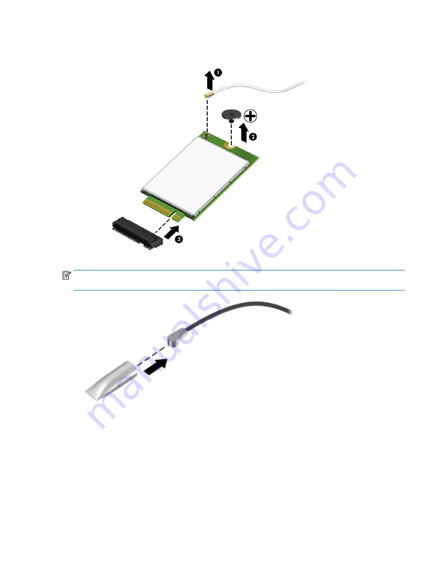
3.
Remove the WLAN module by pulling the module away from the slot at an angle (3).
NOTE:
If the WLAN antennas are not connected to the terminals on the WLAN module, the protective
sleeves must be installed on the antenna connectors, as shown in the following illustration.
Reverse this procedure to install the WLAN module.
Component replacement procedures
33
Summary of Contents for mt245
Page 4: ...iv Safety warning notice ...
Page 8: ...viii ...
Page 26: ...18 Chapter 3 Illustrated parts catalog ...
Page 64: ...56 Chapter 5 Removal and replacement procedures for Authorized Service Provider parts ...
Page 70: ...62 Chapter 6 Computer Setup BIOS and MultiBoot ...
Page 72: ...64 Chapter 7 Device management ...
Page 76: ...68 Chapter 8 Diagnostics and Troubleshooting ...
Page 80: ...72 Chapter 10 Adding an Image Restore Tool ...
Page 88: ...80 Chapter 12 Statement of Volatility ...
Page 92: ...84 Chapter 13 Power cord set requirements ...
Page 94: ...86 Chapter 14 Recycling ...
Page 98: ...90 Index ...


