c.
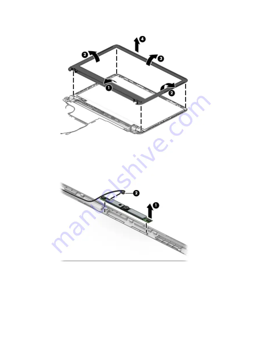
Remove the display bezel (4).
2.
To remove the webcam/microphone module:
a.
Position the display assembly with the top edge toward you.
b.
Lift to disengage the adhesive that secures the webcam/microphone module to the display, and
then remove the module (1) enough to disconnect the cable.
c.
Disconnect the cable (2) from the module.
3.
To remove the display panel:
a.
Remove the four Phillips PM2.0×2.4 screws that secure the display panel to the enclosure.
50
Chapter 5 Removal and replacement procedures for Authorized Service Provider parts
Summary of Contents for mt245
Page 4: ...iv Safety warning notice ...
Page 8: ...viii ...
Page 26: ...18 Chapter 3 Illustrated parts catalog ...
Page 64: ...56 Chapter 5 Removal and replacement procedures for Authorized Service Provider parts ...
Page 70: ...62 Chapter 6 Computer Setup BIOS and MultiBoot ...
Page 72: ...64 Chapter 7 Device management ...
Page 76: ...68 Chapter 8 Diagnostics and Troubleshooting ...
Page 80: ...72 Chapter 10 Adding an Image Restore Tool ...
Page 88: ...80 Chapter 12 Statement of Volatility ...
Page 92: ...84 Chapter 13 Power cord set requirements ...
Page 94: ...86 Chapter 14 Recycling ...
Page 98: ...90 Index ...


