


Endurance Boot Flow Charts
B-1
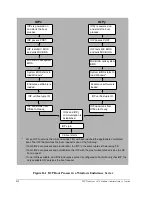
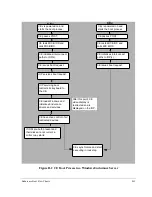
This appendix shows the Endurance server boot flow charts referenced in
Chapter 2
. The IOP
and CE flow charts detail the boot process for the Endurance server. The flow charts assume a
normal system with all Endurance server components powered on and installed and configured
properly. The flow charts also assume that the Endurance server is booting using the default
system configuration.
Endurance Boot
Flow Charts
B
Summary of Contents for NetServer AA 6200
Page 1: ...HP Netserver AA Solution Administrator s Guide HP Part Number 5971 3014 Printed in April 2001 ...
Page 8: ......
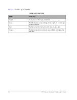
Page 11: ...Tables xi A 3 Firmware LED A 3 A 4 Fiber LEDs A 4 ...
Page 12: ......
Page 14: ......
Page 18: ...xviii HP Netserver AA Solution Administrator s Guide ...
Page 88: ......
Page 180: ...6 8 HP Netserver AA Solution Administrator s Guide Figure 6 2 Sample Endurance Configuration ...
Page 210: ......
Page 216: ......
Page 248: ......
Page 256: ......
Page 262: ......


