


Commands
5-11
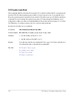
CE Disable Auto Synch
This command disables Auto Synch for a specific CE. Auto Synch allows the second CE to
automatically attempt to synchronize with the running CE. If you disable Auto Synch, you
cannot synchronize that CE into the Endurance server until you issue a CE Enable Auto Synch
command. If you are setting this option to prevent a CE from joining the Endurance server
configuration, make sure that you disable
both
Auto Boot (page
5-10
) and Auto Synch on that
CE.
By default, Auto Synch is
true
(enabled).
Command
CE
n
Disable Auto Synch From IOP
x
Console Syntax
MTCCONS CE
n
Disable Auto Synch From IOP
x
Variables
n
– the ID number of the CE (1 or 2)
x
– the ID number of the IOP (1 or 2)
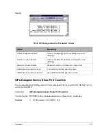
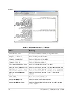
Results
To verify that Auto Synch is disabled for CE
n
, issue a CE
n
Show Auto Synch
or CE
n
Show Parameters command from either IOP.
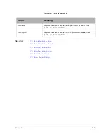
See Also
CE Disable Auto Boot
CE Enable Auto Synch
CE Show Auto Synch
CE Show Parameters
Summary of Contents for NetServer AA 6200
Page 1: ...HP Netserver AA Solution Administrator s Guide HP Part Number 5971 3014 Printed in April 2001 ...
Page 8: ......
Page 11: ...Tables xi A 3 Firmware LED A 3 A 4 Fiber LEDs A 4 ...
Page 12: ......
Page 14: ......
Page 18: ...xviii HP Netserver AA Solution Administrator s Guide ...
Page 88: ......
Page 180: ...6 8 HP Netserver AA Solution Administrator s Guide Figure 6 2 Sample Endurance Configuration ...
Page 210: ......
Page 216: ......
Page 248: ......
Page 256: ......
Page 262: ......


