3.
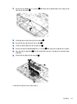
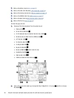
Remove the four Phillips M2.0 × 3.5 screws (3) that secure the system board to the computer.
4.
Release the USB board cable and the RJ-45 board cable from the computer (1). The cables are secured
with double-sided tape.
5.
Lift the left edge of the system board (2), and then pull the board up and to the left to remove it from the
computer (3).
Reverse this procedure to install the system board and USB door.
Top cover with keyboard
The top cover with keyboard remains after removing all other spare parts from the computer. In this section,
the first table provides the main spare part number for the top cover/keyboards. The second table provides
the country codes.
Table 6-15
Top cover with keyboard descriptions and part numbers
Description
Spare part number
Top cover with keyboard for use in ceramic white models:
Top cover with keyboard
65

