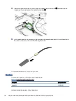
5.
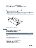
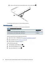
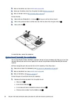
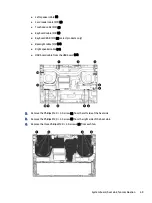
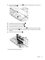
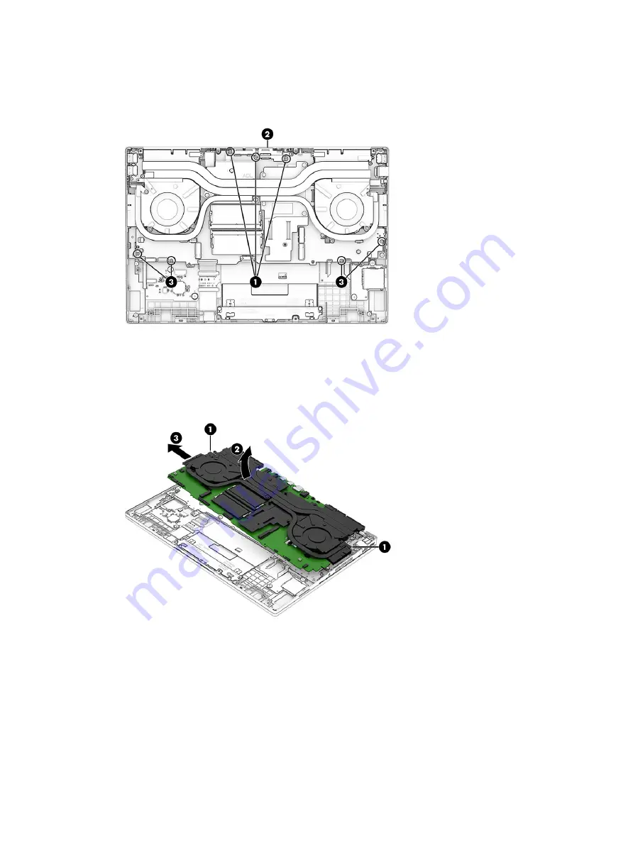
Remove the rear ports bracket by removing the three Phillips M2.0 × 5.0 screws (1), and then removing
the bracket (2).
6.
Remove the four Phillips M2.0 × 3.5 screws (3) that secure the system board to the computer.
7.
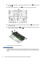
Release the USB board cable and the RJ-45 board cable from the computer (1). The cables are secured
with double-sided tape.
8.
Lift the left edge of the system board (2), and then pull the board with heat sink and fans up and to the
left to remove the assembly from the computer (3).
To install the system board, reverse this procedure.
RJ-45 (network) board
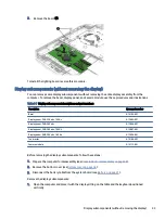
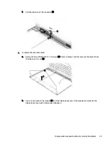
To remove the RJ-45 (network) board, use this procedure and illustration. Before removing the board, you
can remove the system board, heat sink, and fans as an assembly so you do not have to disturb the thermal
material.
50
Chapter 6 Removal and replacement procedures for authorized service provider parts

