background image


Front components 

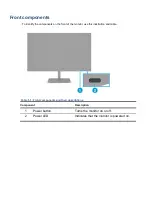
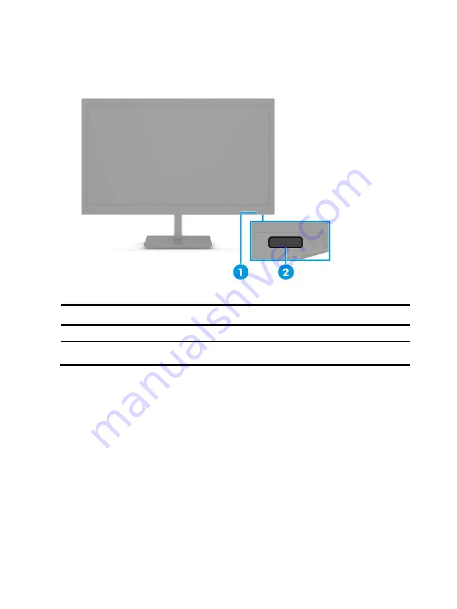
To identify the components on the front of the monitor, use this illustration and table. 


Table 1-1: Front components and their descriptions 

Component 

Description 

1


Power button


Turns the monitor on or off.


2


Power LED


Indicates that the monitor is powered on.


Summary of Contents for P24v G5

Page 1: ...Maintenance and Service Guide P24v G5 model SUMMARY This guide provides information about spare parts removal and replacement of parts diagnostic tests problem troubleshooting and more ...

Page 2: ...tates and other countries The information contained herein is subject to change without notice The only warranties for HP products and services are set forth in the express warranty statements accompanying such products and services Nothing herein should be construed as constituting an additional warranty HP shall not be liable for technical or editorial errors or omissions contained herein First ...

Page 3: ...ct to the customer 2 2 Monitor features 3 Features 3 Front components 4 Rear components 5 Locating the serial number and product number 6 3 Illustrated parts catalog 7 How to order parts 8 4 Removal and replacement procedures 9 Preparation for disassembly 9 Rear Cover 10 Power board 13 Connector repair 17 HDMI connector J3 18 Stick Gasket on the Shielding for HDMI 19 Function test 20 Support and t...

Page 4: ...ical components are sensitive to electrostatic discharge ESD Follow ESD safety procedures while handling these parts Some products contain more than one battery Do not disassemble or expose a battery to high temperatures such as throwing into fire or the battery may explode Refer to government requirements for battery recycling or disposal This information provides general service information for ...

Page 5: ... is a legal requirement by the EU European Union for the global electronics industry sold in the EU and other countries Any electrical and electronics products launched in the market after June 2006 should meet this RoHS requirement Products launched in the market before June 2006 are not required to be compliant with RoHS parts If the original parts are not RoHS complaint the replacement parts ca...

Page 6: ...uded VGA video input cable included in select regions A 4 way on screen display OSD controller that you can reconfigure to quickly allow selection of three most commonly used operations Plug and Play capability if supported by your operating system VESA mounting bracket for attaching the monitor head to a wall mount device or swing arm Security cable slot on the rear of the monitor for an optional...

Page 7: ...mponents on the front of the monitor use this illustration and table Table 1 1 Front components and their descriptions Component Description 1 Power button Turns the monitor on or off 2 Power LED Indicates that the monitor is powered on ...

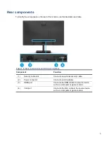
Page 8: ...nents and their descriptions Component Function 1 Security cable slot Connects an optional security cable 2 Power connector Connects an AC adapter 3 HDMI port Connects the HDMI cable to a source device such as a computer or game console 4 VGA port Connects the VGA cable to the source device such as a computer or game console ...

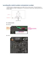
Page 9: ...PEC label 1 and Barcode label 2 are located on the rear of the monitor The serial number and product number are located on a Safety label You may need these numbers when contacting HP about the monitor model For worldwide models Barcode label Spec label ...

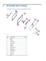
Page 10: ...nitor major components use this illustration and table Item Description Qty 1 DECO 1 2 PANEL 1 3 Mid FRAME 1 4 LENS PWR 1 5 SPS BD 1 6 MAIN BD 1 7 CONTROL BD 1 8 MAIN SHD 1 9 REAR COVER 1 10 CVR VESA 1 11 COLUMN 1 12 BASE 1 1 2 3 4 5 6 7 8 9 10 12 11 ...

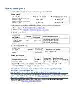
Page 11: ...n Component distributor Distributer part number HDMI Farnell RS Molex 2086581001 Gasket by distributor Component Description Location Component Distributor Part number of Manufacturer Distributor Gasket for HDMI SHD Farnell RS 3020812 Specification Gasket EMI Shielding 8 mm Width 12 mm Height 1 m Length 80 dB To replace HDMI must need a gasket stick on shielding NOTE The connector may need to be m...

Page 12: ...ce information and precautions sections in the Getting started chapter of this guide 2 Clean the room for disassembly 3 Identify the disassembly area 4 Check the position that the monitors are to be placed along with the number of monitors Prepare the area for material flow according to the disassembly layout 5 Be sure to have the following equipment and materials Press fixture Working table Screw...

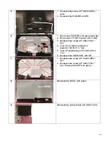
Page 13: ...Rear Cover No Picture Operation 1 Disassembly STAND 2 Disassembly VESA COVER from RC 3 1 Disassembly screw 8F 00729 011 4pcs 8F MA324 5R5 2pcs 2 Disassembly RC from MF 4 Disconnect OSD BD with LVDS ...

Page 14: ... with LVDS 3 Disassemble screw 8F 009J7 001 2pc 4 Tear off conductive adhesive tape 4G 13A09 011 2pc 5 Tear off acetate tape 3H 04054 081 1pc 6 Disassemble MAIN SHD with MF 7 1 Disassemble screw 8F 5A224 4R5 9pc 2 Disassemble screw 8F 009J7 001 2pc Disassemble MF with panel 8 Disassemble DECO with panel 9 Disassemble safety Mylar 4K 5M301 001 ...

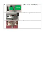
Page 15: ...10 Unfixed screw 8F VC434 9R0 6pcs 11 Unfixed screw 8F 205B4 019 2pc 12 Take out everything ITF BD PWR BD ...

Page 16: ...sembly on page 9 Remove the power board Locate the part number location on the board IMPORTANT Repairing must operate by professional repairers in HP repair center not applicable for end user The primary side is the high voltage area please take care when repair Front and Back view After repaired must check PSU function is ordinary Power BD PN Primary side Primary side ...

Page 17: ...ead to malfunctions The fusion point of Lead Free solder is requested Repairing with conventional lead wire may cause damage Work quickly to avoid overheating the circuit board as soon as you confirm the steady soldering condition Keep the soldering iron tip clean and well tinned and when replacing parts A close inspection of the circuit board revealed look in good condition After repaired must do...

Page 18: ...cause product no work The C701 locations are identified below 1 You must disconnect the power cord from the power source before opening the monitor to prevent component damage 2 Use Multimeter measure whether EL capacitors still have charge Before repairing must discharging it C701 ...

Page 19: ...e PCB 4 Place new component on the location and must check polarity match PCB print After repaired please double check whether polarity match PCB print solder empty and unnecessary solder after soldering must remove Power Board ...

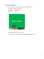
Page 20: ...in board board part number 5E 5M501 00x The connectors identifiers are as follows Connector Location HDMI J3 Before repairing connectors follow these steps Prepare the monitor for disassembly See Preparation for disassembly on page 9 J1 J3 Main Board ...

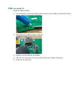
Page 21: ...e soldering pump to remove as much solder as possible from the pin 2 Use a hot air gun to melt the solder on the pins 3 Lift the J3 connector from the circuit board 4 Place the new component on the circuit board Be sure that it matches the footprint 5 Solder the new component ...

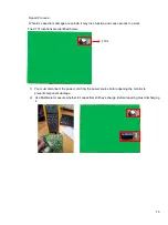
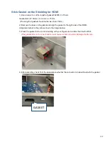
Page 22: ... the gasket and align the gasket to the right side of the HDMI Alignment refers to the yellow arrow in the image below 3 Press the gasket to the end of shielding with your fingers and confirm that it will not fall If the gasket falls on the inner boards it will cause a short circuit and damage the Monitor 4 After assembly check from the appearance whether the connector is indeed fixed with the gas...

Page 23: ...air be sure to confirm that all functions are working Table 4 1 Function test Test item Operating description Tool used HDMI test Confirm whether image displays and sound plays correctly on the monitor Computer or DVD player ...

Page 24: ...too low Open the OSD menu and select Brightness to adjust the brightness scale as needed Check Video Cable is displayed on screen Monitor video cable is disconnected Connect the appropriate video signal cable between the computer and monitor Be sure that the computer power is off while you connect the video cable Input Signal Out of Range is displayed on screen Video resolution and or refresh rate...

Page 25: ...arts 7 parts ordering 8 power board removal 13 power light location 4 precautions 1 preparation for disassembly 9 R RC removal 12 rear components 5 removal power board 13 RC 12 removal and replacement procedures 9 returning to customer 2 RoHS 2002 95 EC requirements 2 S safety information 1 serial number location 6 service information 1 spare parts 7 support and troubleshooting 21 T troubleshootin...

Reviews: