


Item
Component
Spare part
number
For use in models with a backlit keyboard:
●
For use in French Canada
809032-DB1
●
For use in Saudi Arabia
809032-171
●
For use in Turkey
809032-141
●
For use in the United States
809032-001
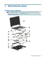
(3)
Optical Drive Cable Kit
811199-001
(4)
Touchpad
813987-001
(5)
Power button board
(includes cable)
809033-001
(6)
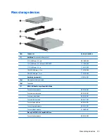
Hard drive
(does not include bracket):
NOTE:
The hard drive bracket and connector are available using spare part number 809296-001.
2-TB, 5400-rpm, 2.5-inch
801808-005
1-TB, 5400-rpm, 2.5-inch, hybrid 8 GB SSD
731999-005
1-TB, 5400-rpm, 2.5-inch
778192-005
750 GB, 5400 rpm hard drive, 2.5 inch
778190-005
500-GB, 5400-rpm, 7 mm
778186-005
(7)
USB board
(includes cable)
809409-001
(8)
System board
(includes replacement thermal materials)
All system boards use the following part numbers:
xxxxxx-001: Without the Windows operating system
xxxxxx-501: Windows 8.1 Standard
xxxxxx-601: Windows 8.1 Professional
For use in models with 2 GB of discrete graphics memory:
●
AMD A10-8700P processor
809408-xxx
●
AMD A8-7410 processor
809407-xxx
●
AMD A6-6310 processor
809339-xxx
For use in models with UMA graphics memory:
●
AMD A10-8700P processor
809338-xxx
●
AMD A8-7410 processor
809337-xxx
●
AMD A6-6310 processor
809336-xxx
●
AMD A4-6210 processor
809335-xxx
(9)
Fan
806747-001
(10)
Speakers
(includes left and right speakers and cable)
809037-001
(11)
WLAN module
Intel Dual Band Wireless-AC 7265 802.11 ac 2x2 WiFi + BT 4.0 Combo Adapter (non vPRO)
784644-005
Computer major components
17
Summary of Contents for Pavilion 2159m
Page 1: ...HP Pavilion Notebook AMD Maintenance and Service Guide ...
Page 4: ...iv Safety warning notice ...
Page 8: ...14 Recycling 97 Index 99 viii ...
Page 12: ...4 Chapter 1 Product description ...
Page 32: ...24 Chapter 3 Illustrated parts catalog ...
Page 40: ...32 Chapter 5 Removal and replacement procedures for Customer Self Repair parts ...
Page 80: ...72 Chapter 8 Using Setup Utility BIOS in Windows 8 1 ...
Page 88: ...80 Chapter 10 Backing up restoring and recovering in Windows 8 1 ...
Page 100: ...92 Chapter 12 Specifications ...
Page 104: ...96 Chapter 13 Power cord set requirements ...
Page 106: ...98 Chapter 14 Recycling ...
Page 110: ...102 Index ...


