2
.
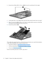
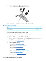
Remove the two Phillips PM2.5×5.0 screws
(2)
that secure the system board to the computer.
3
.
Use the optical drive connector
(1)
to lift the right side of the system board until it rests at an angle.
4
.
Release the system board
(2)
by sliding it to the right at an angle until the connectors on the left side
of the system board disengage from the base enclosure.
5
.
Remove the system board
(3)
.
When replacing the system board, be sure that the following components are removed from the defective
system board and installed on the replacement system board:
●
ExpressCard assembly (see
ExpressCard assembly on page 94
)
●
Fan/heat sink assembly (see
Fan/heat sink assembly on page 96
●
Processor (see
Reverse the preceding procedure to install the system board.
92 Chapter
4
Removal and replacement procedures
Summary of Contents for PAVILION DV2500
Page 1: ...HP Pavilion dv2500 Notebook PC Maintenance and Service Guide ...
Page 4: ...iv Safety warning notice ...
Page 172: ......

