7.
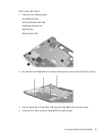
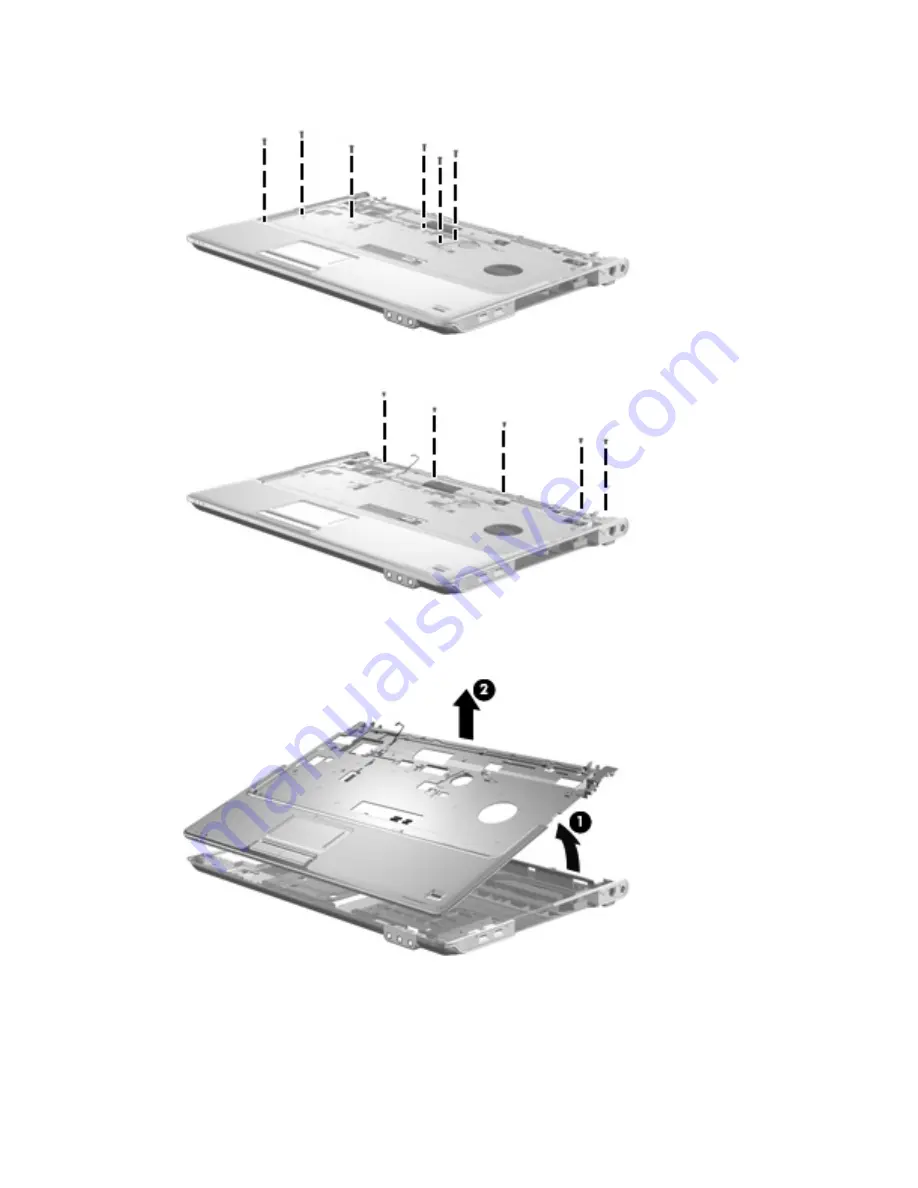
Remove the six Phillips PM2.5×6.0 screws that secure the top cover to the base enclosure.
8.
Remove the five Phillips PM2.5×4.0 screws that secure the top cover to the base enclosure.
9.
Lift the rear edge of the top cover
(1)
until it disengages from the computer, and then lift the top
cover
(2)
up and remove it.
Reverse this procedure to install the top cover.
84
Chapter 4 Removal and replacement procedures
Summary of Contents for Pavilion dv7-1100 - Entertainment Notebook PC
Page 1: ...HP Pavilion dv7 Entertainment PC Maintenance and Service Guide ...
Page 4: ...iv Safety warning notice ...
Page 26: ...Computer major components 18 Chapter 3 Illustrated parts catalog ...
Page 113: ...Reverse this procedure to install the heat sink Component replacement procedures 105 ...
Page 167: ...Universal Serial Bus Pin Signal 1 5 VDC 2 Data 3 Data 4 Ground Universal Serial Bus 159 ...
Page 181: ......


