Removal and Replacement Procedures
Maintenance and Service Guide
5–73
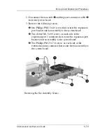
2. Disconnect the fan cable
1
and the power connector cable
2
from the system board.
3. Remove the following screws:
3
One Phillips PM2.5×4.0 screw that secures the expansion
port bracket and fan assembly to the system board
4
Two slotted M1.5×9.0 screws on each side of the
expansion port 2 connector that secure the expansion port
bracket and fan assembly to the system board
5
Two Phillips PM2.5×7.0 screws on each side of the
external monitor connector that secure the fan assembly to
the system board
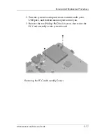
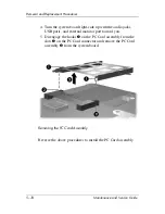
Removing the Fan Assembly Screws
Summary of Contents for Pavilion dv8300
Page 60: ...3 4 Maintenance and Service Guide Illustrated Parts Catalog Computer Major Components ...
Page 62: ...3 6 Maintenance and Service Guide Illustrated Parts Catalog Computer Major Components ...
Page 64: ...3 8 Maintenance and Service Guide Illustrated Parts Catalog Computer Major Components ...
Page 66: ...3 10 Maintenance and Service Guide Illustrated Parts Catalog Computer Major Components ...

