

EL-MF877-00 Page 2
Template Revision B
PSG instructions for this template are available at
EL-MF877-01
Components, parts and materials containing
refractory ceramic fibers
0
Components, parts and materials containing
radioactive substances
0
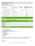
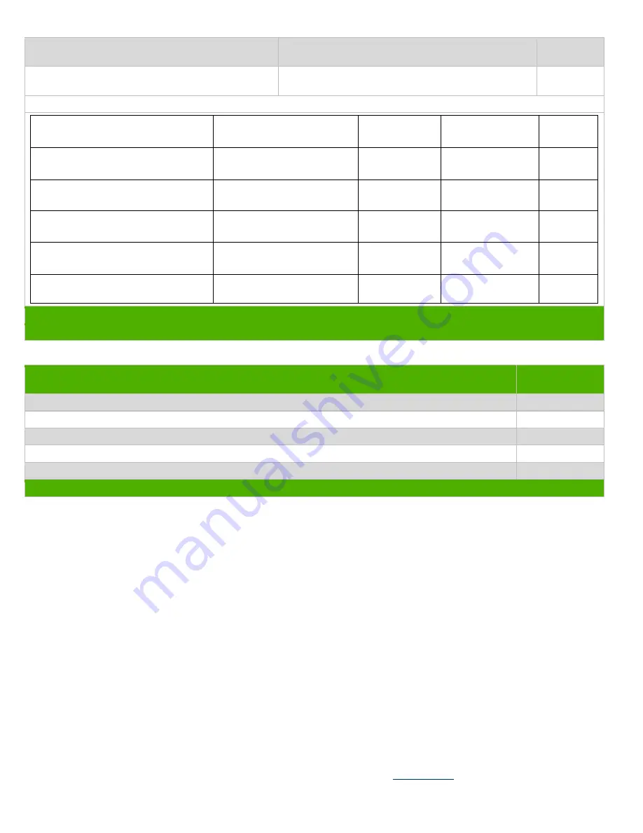
1.3 Markings for plastic parts greater than 25 grams
Plastic Part Name
Plastic Part Description
Weight
(grams)
ISO 11469:2000
Plastic Part Mark
Optional:
Photo
NEPTUNE2_MAIN_BEZEL
Main bezel
235
>ABS<
NEPTUNE2_TRIM_BEZEL
main bezel trim
45
>ABS<
NEPTUNE2_COSMETIC_BEZEL
main bezel cosmetic part
34
>ABS<
NEPTUNE2_TOP_CAP_BASE
top cap
215
>ABS<
Fan Frame
CPU fan frame
36
>PBT-GF30-
FR(17)<
2.0 Tools Required
List the type and size of the tools that would typically be used to disassemble the product to a point where components
and materials requiring selective treatment can be removed.
Tool Description
Tool Size (if
applicable)
Description #1 Phillips screw driver
NO 2
Description #2
Description #3
Description #4
Description #5
3.0 Product Disassembly Process
3.1 List the basic steps that should typically be followed to remove components and materials requiring selective treatment:
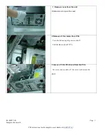
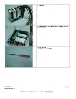
1. Remove cover from the unit
2. Remove all the cables from PCA
3. remove PCI & PCI-E card from the PCA
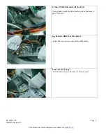
4. Remove HDD from the system Remove ODD from PCA
5. take off Front Panel
6. Take off ODD
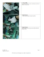
7. Take off Cooler
8. Take off CMOS battery
9. Take off PS from the Unit
10. cut off wire tie
11. open PS
3.2 Optional Graphic. If the disassembly process is complex, insert a graphic illustration below to identify the items
contained in the product that require selective treatment (with descriptions and arrows identifying locations).


