


Removing or Installing
an Add-in Card
An add-in card is a circuit board, such as a PCI or an
AGP card, that fits into a PC add-in card slot. Your PC
contains several add-in card slots that can be used to
add components to your PC. The PC component
configurations vary by model.
WARNING: Do not overload the system
by installing add-in cards that draw
excessive current. The system is designed
to provide 2 amps (average) of +5 V
power for each board/card in the
computer. The total +5 V current draw in a
fully loaded system (one with all add-in
card slots filled) must not exceed the total
number of slots multiplied by 2 amps.
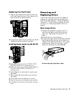
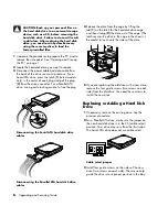
Removing an Add-in Card
1
Complete the procedures to prepare the PC, and to
remove the side panel. See “Opening and Closing
the PC“ on page 1.
2
Gently lay the PC on its side.
3
Inside the PC, locate the add-in card slots on the
motherboard.
4
Release the latch that retains the cards by pressing
the two tabs at the top of the add-in slots inside
the chassis. Some PCs use a screw instead of the
retaining latch to secure each add-in card; remove
the screw.
5
Holding the card at each end, carefully rock it back
and forth until the connectors pull free from the
socket, and then remove the card. Be sure not to
scrape the card against the other components.
Store the old card in the anti-static packaging that
contained your new card.
6
If you are not replacing the old add-in card with a
new add-in card, close the open slot by inserting
the metal slot cover into the opened slot. Replace
the latch or insert the screw.
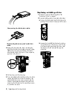
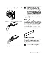
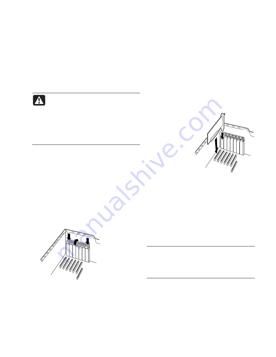
Installing an Add-in Card
1
Align the edge of
the add-in card
with the slot on the
chassis and gently
but firmly press the
card straight down
into the add-in
card slot. The
whole connector
should be seated
properly in the
card slot.
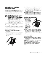
2
Replace the latch by pressing in on the square tabs
on the outside of the chassis. The latch should move
down so that it locks into position over the cards. If
it does not latch, check that each card is completely
seated into its card slot.
Or
Insert the retaining screw.
3
Set the chassis upright.
4
Complete the procedures to replace the side panel,
and close the PC. See “Opening and Closing the
PC“ on page 1.
NOTE:
If the new card or device isn’t working, read
through the card manufacturer’s installation
instructions, and recheck all connections, including
those to the card, power supply, keyboard, and
monitor.
Upgrading and Servicing Guide
9
Summary of Contents for Pavilion Ultimate d4900 - Desktop PC
Page 1: ...Upgrading and Servicing Guide ...
Page 4: ...iv Upgrading and Servicing Guide ...
Page 15: ......
Page 16: ...Part Number 5991 7205 ...


