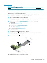
background image

Fan

Table 5-7

  Fan spare part information

Description

Spare part number

Services the processor

L96492-001

Before removing the fan, follow these steps:

1.

Shut down the computer. If you are unsure whether the computer is off or in Hibernation, turn 
the computer on, and then shut it down through the operating system.

2.

Disconnect all external devices connected to the computer.

3.

Disconnect the power from the computer by first unplugging the power cord from the AC outlet, and then 
unplugging the AC adapter from the computer.

4.

Remove the bottom cover (see 

Bottom cover on page 39

).

5.

Remove the battery (see 
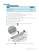
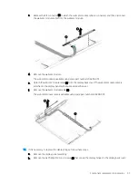
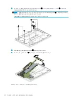
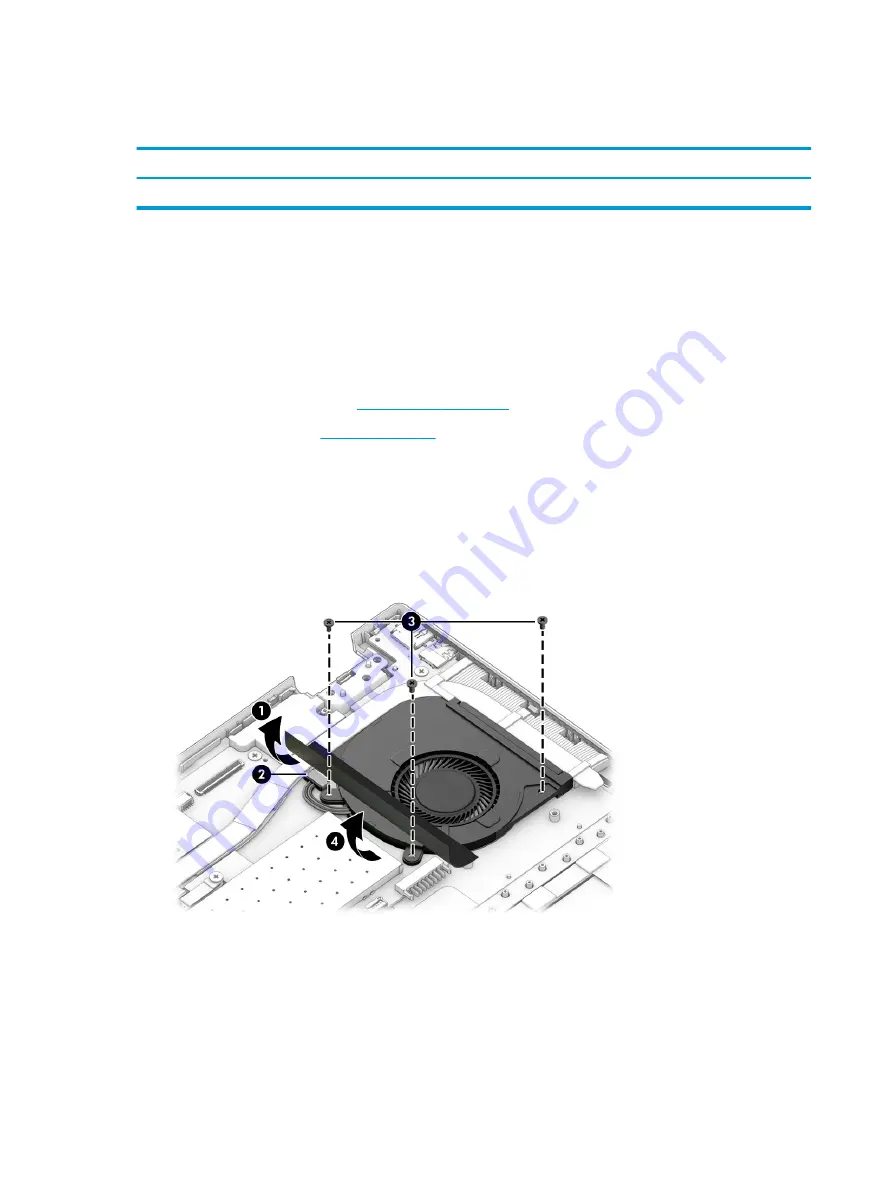
Battery on page 41

).

Remove the fan:

1.

Fold back the shield (1) that covers the fan cable and fan screws.

2.

Disconnect the fan cable (2) from the system board.
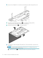
3.

Remove the three Phillips M2.0×4.7 screws (3) that secure the fan to the system board.
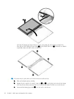
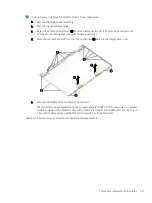
4.

Lift the left side of the fan (4) until it clears the memory module shield, and then remove the fan.

Reverse this procedure to install the fan.

60

Chapter 5   Removal and replacement procedures

Summary of Contents for Pavilion x360 14 Series

Page 1: ...Maintenance and Service Guide HP Pavilion x360 14 Convertible PC IMPORTANT This document is intended for HP authorized service providers only ...

Page 2: ...n First Edition April 2020 Document Part Number L86982 001 Product notice This guide describes features that are common to most models Some features may not be available on your computer Not all features are available in all editions or versions of Windows Systems may require upgraded and or separately purchased hardware drivers software or BIOS update to take full advantage of Windows functionali...

Page 3: ...a hard flat surface Do not allow another hard surface such as an adjoining optional printer or a soft surface such as pillows or rugs or clothing to block airflow Also do not allow the AC adapter to contact the skin or a soft surface such as pillows or rugs or clothing during operation The computer and the AC adapter comply with the user accessible surface temperature limits defined by applicable ...

Page 4: ...iv Safety warning notice ...

Page 5: ...bels 13 3 Illustrated parts catalog 15 Computer major components 16 Display components 31 Miscellaneous parts 33 4 Removal and replacement procedures preliminary requirements 34 Tools required 34 Service considerations 34 Plastic parts 34 Cables and connectors 34 Drive handling 35 Electrostatic discharge damage 35 Packaging and transporting guidelines 36 Workstation guidelines 37 Equipment guideli...

Page 6: ...Restoring factory settings in Computer Setup 77 Updating the BIOS 78 Determining the BIOS version 78 Downloading a BIOS update 78 Changing the boot order using the f9 prompt 79 TPM BIOS settings select products only 79 Using HP Sure Start select products only 80 7 Backing up restoring and recovering 81 Backing up information and creating recovery media 81 Using Windows tools 81 Using the HP Cloud ...

Page 7: ...HP PC Hardware Diagnostics UEFI to a USB flash drive 88 Downloading the latest HP PC Hardware Diagnostics UEFI version 88 Downloading HP PC Hardware Diagnostics UEFI by product name or number select products only 89 Using Remote HP PC Hardware Diagnostics UEFI settings select products only 89 Downloading Remote HP PC Hardware Diagnostics UEFI 89 Downloading the latest Remote HP PC Hardware Diagnos...

Page 8: ...viii ...

Page 9: ...0 1080 antiglare white light emitting diode WLED UWVA 72 eDP 1 3 PSR slim display panel with narrow bezel typical brightness 400 nits 14 0 inch LCD FHD 1920 1080 antiglare WLED UWVA 72 eDP flat display panel with narrow bezel typical brightness 400 nits 14 0 inch LCD FHD 1920 1080 antiglare WLED UWVA 45 eDP flat display panel with narrow bezel typical brightness 250 nits 14 0 inch LCD HD 1366 768 ...

Page 10: ...1 Type A ports 2 USB 3 1 Gen 1 Type C port Expansion One next generation form factor NGFF slot for a solid state drive One NGFF slot for a WLAN module One NGFF slot for a WWAN module select products only Media card reader Subcriber identity module SIM slot Nano SIM Multimedia card HP Multi Format Digital Media Card Reader Keyboard pointing devices Island style standard notebook keyboard in ash gra...

Page 11: ...ws 10 Home 64 bit Single Language Africa Market PPP Windows 10 Home 64 bit Single Language Asia Pacific Emerging Market PPP Windows 10 Home 64 bit Single Language India Market PPP Windows 10 Home 64 bit Single Language Indonesia Market PPP Windows 10 Home 64 bit Single Language Value Africa Market PPP Windows 10 Home 64 bit Single Language Value Asia Pacific Emerging Market PPP Windows 10 Home 64 ...

Page 12: ...r Type device manager in the taskbar search box and then select the Device Manager app A list displays all the devices installed on the computer For information about system hardware components and the system BIOS version number press fn esc select products only Locating software To find out what software is installed on the computer Right click the Start button and then select Apps and Features 4...

Page 13: ...connector provides data transfer and even when the computer is off charges most products such as a cell phone camera activity tracker or smartwatch and Connects a display device that has a USB Type C connector providing DisplayPort output NOTE Cables adapters or both purchased separately might be required 4 USB port Connects a USB device such as a cell phone camera activity tracker or smartwatch a...

Page 14: ...nects an optional headset microphone This jack does not support optional standalone microphones WARNING To reduce the risk of personal injury adjust the volume before putting on headphones earbuds or a headset For additional safety information see the Regulatory Safety and Environmental Notices To access this guide Type HP Documentation in the taskbar search box and then select HP Documentation NO...

Page 15: ...ions Component Description 1 WWAN antennas select products only Send and receive wireless signals to communicate with WWANs 2 WLAN antennas Send and receive wireless signals to communicate with WLANs 3 Internal microphones Record sound 4 Camera Allows you to video chat record video and record still images Some cameras also allow a facial recognition logon to Windows instead of a password logon NOT...

Page 16: ...d 1 Type touchpad settings in the taskbar search box and then press enter 2 Using an external mouse click the touchpad button or Press the Tab key repeatedly until the pointer rests on the touchpad button Then press the spacebar to select the button Table 2 4 Touchpad components and their descriptions Component Description 1 Touchpad zone Reads finger gestures to move the pointer or activate items...

Page 17: ...s off Off Computer sound is on 3 Power light On The computer is on Blinking select products only The computer is in the Sleep state a power saving state The computer shuts off power to the display and other unnecessary components Off Depending on the computer model the computer is off in Hibernation or in Sleep Hibernation is the power saving state that uses the least amount of power Keyboard area...

Page 18: ...d their descriptions Component Description 1 Speakers Produce sound 2 Fingerprint reader select products only Allows a fingerprint logon to Windows instead of a password logon Swipe down across the fingerprint reader IMPORTANT To prevent fingerprint logon issues make sure when registering a fingerprint that all sides of the finger are registered by the fingerprint reader 10 Chapter 2 Components ...

Page 19: ...on to turn on the computer When the computer is on press the button briefly to initiate Sleep When the computer is in the Sleep state press the button briefly to exit Sleep select products only When the computer is in Hibernation press the button briefly to exit Hibernation IMPORTANT Pressing and holding down the power button results in the loss of unsaved information If the computer has stopped r...

Page 20: ...t Description Vent Enables airflow to cool internal components NOTE The computer fan starts up automatically to cool internal components and prevent overheating It is normal for the internal fan to cycle on and off during routine operation 12 Chapter 2 Components ...

Page 21: ... the bottom of a tablet kickstand Service label Provides important information to identify the computer When contacting support the serial number the product number or the model number may be requested Locate this information before contacting support The service label will resemble one of the following examples Refer to the illustration that most closely matches the service label on the computer ...

Page 22: ...riod Regulatory label s Provide s regulatory information about the computer Wireless certification label s Provide s information about optional wireless devices and the approval markings for the countries or regions in which the devices have been approved for use 14 Chapter 2 Components ...

Page 23: ...TE HP continually improves and changes product parts For complete and current information about supported parts for the computer go to http partsurfer hp com select the country or region and then follow the on screen instructions 15 ...

Page 24: ...information Item Component Spare part number 1 Display assembly The display assembly is available as spare parts at the subcomponent level only For more display assembly spare part information see Display components on page 31 16 Chapter 3 Illustrated parts catalog ...

Page 25: ...or use in Italy L96530 061 For use in Japan L96530 291 For use in Latin America L96530 161 For use in the Netherlands L96530 B31 For use in Portugal L96530 131 For use in Russia L96530 251 For use in Saudi Arabia L96530 171 For use in Slovenia L96530 BA1 For use in South Korea L96530 AD1 For use in Spain L96530 071 For use in Switzerland L96530 BG1 For use in Taiwan L96530 AB1 For use in Thailand ...

Page 26: ...orea L96528 AD1 For use in Spain L96528 071 For use in Switzerland L96528 BG1 For use in Taiwan L96528 AB1 For use in Thailand L96528 281 For use in the Ukraine L96528 BD1 For use in the United Kingdom L96528 031 For use in the United States L96528 001 Keyboard top cover with backlight in ash silver keyboard and forest teal top cover finishes includes backlight cable and keyboard cable For use in ...

Page 27: ...6527 031 For use in the United States L96527 001 Keyboard top cover in ash silver keyboard and forest teal top cover finishes includes keyboard cable For use in Belgium L96526 A41 For use in Canada L96526 DB1 For use in the Czech Republic and Slovakia L96526 FL1 For use in Denmark Finland and Norway L96526 DH1 For use in France L96526 051 For use in Germany L96526 041 For use in Greece L96526 151 ...

Page 28: ...ublic and Slovakia L96524 FL1 For use in Denmark Finland and Norway L96524 DH1 For use in France L96524 051 For use in Germany L96524 041 For use in Greece L96524 151 For use in Hungary L96524 211 For use in India L96524 002 For use in Israel L96524 BB1 For use in Italy L96524 061 For use in Latin America L96524 161 For use in the Netherlands L96524 B31 For use in Portugal L96524 131 For use in Ru...

Page 29: ... For use in Israel L96531 BB1 For use in Italy L96531 061 For use in Latin America L96531 161 For use in the Netherlands L96531 B31 For use in Portugal L96531 131 For use in Russia L96531 251 For use in Saudi Arabia L96531 171 For use in Slovenia L96531 BA1 For use in South Korea L96531 AD1 For use in Spain L96531 071 For use in Switzerland L96531 BG1 For use in Taiwan L96531 AB1 For use in Thaila...

Page 30: ...rea L96529 AD1 For use in Spain L96529 071 For use in Switzerland L96529 BG1 For use in Taiwan L96529 AB1 For use in Thailand L96529 281 For use in the Ukraine L96529 BD1 For use in the United Kingdom L96529 031 For use in the United States L96529 001 Keyboard top cover with backlight in ash silver keyboard and natural silver touchpad finishes includes backlight cable and keyboard cable For use in...

Page 31: ...n the United States L96525 001 Keyboard top cover with backlight in luminous gold finish includes backlight cable and keyboard cable For use only on computer models equipped with a fingerprint reader For use in Belgium L96523 A41 For use in Canada L96523 DB1 For use in the Czech Republic and Slovakia L96523 FL1 For use in Denmark Finland and Norway L96523 DH1 For use in France L96523 051 For use i...

Page 32: ...ium L96522 A41 For use in Canada L96522 DB1 For use in the Czech Republic and Slovakia L96522 FL1 For use in Denmark Finland and Norway L96522 DH1 For use in France L96522 051 For use in Germany L96522 041 For use in Greece L96522 151 For use in Hungary L96522 211 For use in India L96522 002 For use in Israel L96522 BB1 For use in Italy L96522 061 For use in Latin America L96522 161 For use in the...

Page 33: ... use in Greece L96521 151 For use in Hungary L96521 211 For use in India L96521 002 For use in Israel L96521 BB1 For use in Italy L96521 061 For use in Latin America L96521 161 For use in the Netherlands L96521 B31 For use in Portugal L96521 131 For use in Russia L96521 251 For use in Saudi Arabia L96521 171 For use in Slovenia L96521 BA1 For use in South Korea L96521 AD1 For use in Spain L96521 0...

Page 34: ...19 171 For use in Slovenia L96519 BA1 For use in South Korea L96519 AD1 For use in Spain L96519 071 For use in Switzerland L96519 BG1 For use in Taiwan L96519 AB1 For use in Thailand L96519 281 For use in the Ukraine L96519 BD1 For use in the United Kingdom L96519 031 For use in the United States L96519 001 Keyboard top cover in natural silver finish includes keyboard cable For use only on compute...

Page 35: ... L96520 281 For use in the Ukraine L96520 BD1 For use in the United Kingdom L96520 031 For use in the United States L96520 001 Keyboard top cover in natural silver finish includes keyboard cable For use in Belgium L96518 A41 For use in Canada L96518 DB1 For use in the Czech Republic and Slovakia L96518 FL1 For use in Denmark Finland and Norway L96518 DH1 For use in France L96518 051 For use in Ger...

Page 36: ...print reader cable not illustrated L96499 001 7 Fingerprint reader bracket not available as a spare part 8 Speakers include left and right speakers cables and 2 rubber isolators L96508 001 9 Connector board includes USB port and audio out headphone audio in microphone combo jack L96503 001 Connector board cable not illustrated L96501 001 10 System board includes processor graphics subsystem with U...

Page 37: ...d state drive L85366 005 256 GB M 2 2280 PCIe NVMe value solid state drive L85354 005 256 GB 2280 PCIe 3 2 2 NVMe 16 GB 3D Xpoint solid state drive L85356 005 128 GB M 2 2280 SATA 3 solid state drive with TLC L85346 005 15 Solid state drive bracket not available as a spare part 16 Intel XMM 7360 LTE Advanced Cat 9 WWAN module L70670 005 17 WLAN module Intel Wi Fi 6 AX201 ax 2 2 Bluetooth 5 0 MU MI...

Page 38: ...formation continued Item Component Spare part number In natural silver finish L96486 001 22 Rubber feet In ash silver finish L96491 001 In natural silver finish L96489 001 In warm gold finish L96490 001 30 Chapter 3 Illustrated parts catalog ...

Page 39: ...ter models equipped with WWAN capability L96497 001 For use only on computer models not equipped with WWAN capability L96496 001 3 Sensor board L96506 001 4 Touch control board includes double sided adhesive L96505 001 5 Display hinges 2 includes left and right hinges For use only on computer models equipped with an FHD display panel assembly L96494 001 For use only on computer models equipped wit...

Page 40: ...er includes the wireless antenna cables and transceivers In natural silver finish for use only on computer models equipped with an FHD display panel assembly and with WWAN capability L98209 001 In forest teal finish for use only on computer models equipped with an FHD display L96485 001 In natural silver finish for use only on computer models equipped with an FHD display L96483 001 In warm gold fi...

Page 41: ...Zenvo pen in natural silver finish with cable L95614 001 Power cord C5 1 0 m conventional with sticker For use in Argentina L19357 001 For use in Australia L19358 001 For use in Denmark L19360 001 For use in Europe L19361 001 For use in India L19363 001 For use in Israel L19362 001 For use in Italy L19364 001 For use in Japan L19365 001 For use in North America L19367 001 For use in the People s R...

Page 42: ... excessive force during disassembly and reassembly can damage plastic parts Use care when handling the plastic Cables and connectors IMPORTANT When servicing the computer be sure that cables are placed in their proper locations during the reassembly process Improper cable placement can damage the computer Cables must be handled with extreme care to avoid damage Apply only the tension required to u...

Page 43: ...mponents are sensitive to electrostatic discharge ESD Circuitry design and structure determine the degree of sensitivity Networks built into many integrated circuits provide some protection but in many cases ESD contains enough power to alter device parameters or melt silicon junctions A discharge of static electricity from a finger or other conductor can destroy static sensitive devices or microc...

Page 44: ...hand contact transport products in static safe tubes bags or boxes Protect ESD sensitive parts and assemblies with conductive or approved containers or packaging Keep ESD sensitive parts in their containers until the parts arrive at static free workstations Place items on a grounded surface before removing items from their containers Always be properly grounded when touching a component or assembl...

Page 45: ...flexible straps with a minimum of 1 MΩ 10 resistance in the ground cords To provide proper ground wear a strap snugly against the skin at all times On grounded mats with banana plug connectors use alligator clips to connect a wrist strap When standing use foot straps and a grounded floor mat Foot straps heel toe or boot straps can be used at standing workstations and are compatible with most types...

Page 46: ...able 4 2 Shielding protection provided by antistatic bags and floor mats Material Use Voltage protection level Antistatic plastics Bags 1 500 V Carbon loaded plastic Floor mats 7 500 V Metallized laminate Floor mats 5 000 V 38 Chapter 4 Removal and replacement procedures preliminary requirements ...

Page 47: ...lver finish for use only on computer models equipped with WWAN capability L98204 001 In ash silver finish for use only on computer models not equipped with WWAN capability L96488 001 In luminous gold finish L96487 001 In natural silver finish L96486 001 Remove the bottom cover 1 Shut down the computer If you are unsure whether the computer is off or in Hibernation turn the computer on and then shu...

Page 48: ...secure the bottom cover to the keyboard top cover 7 Use a thin plastic tool 1 to separate the front edge of the bottom cover from the keyboard top cover 8 Remove the bottom cover 2 Reverse this procedure to install the bottom cover 40 Chapter 5 Removal and replacement procedures ...

Page 49: ...en shut it down through the operating system 2 Disconnect all external devices connected to the computer 3 Disconnect the power from the computer by first unplugging the power cord from the AC outlet and then unplugging the AC adapter from the computer 4 Remove the bottom cover see Bottom cover on page 39 Remove the battery 1 Remove the five Phillips M2 0 4 7 screws that secure the battery to the ...

Page 50: ... the location of the battery hook 3 The battery hook can become dislodged when replacing the battery The battery hook is available using spare part number L97983 001 Reverse this procedure to install the battery 42 Chapter 5 Removal and replacement procedures ...

Page 51: ...sure whether the computer is off or in Hibernation turn the computer on and then shut it down through the operating system 2 Disconnect all external devices connected to the computer 3 Disconnect the power from the computer by first unplugging the power cord from the AC outlet and then unplugging the AC adapter from the computer 4 Remove the bottom cover see Bottom cover on page 39 5 Remove the ba...

Page 52: ...85366 005 256 GB M 2 2280 PCIe NVMe value solid state drive L85354 005 256 GB 2280 PCIe 3 2 2 NVMe 16 GB 3D Xpoint solid state drive L85356 005 128 GB M 2 2280 SATA 3 solid state drive with TLC L85346 005 Before removing the solid state drive follow these steps 1 Shut down the computer If you are unsure whether the computer is off or in Hibernation turn the computer on and then shut it down throug...

Page 53: ...from the retention clips built onto the system board 2 Remove the solid state drive shield 2 3 Remove the Phillips M2 0 2 1 screw 1 that secures the solid state drive to the system board 4 Remove the solid state drive 2 by sliding it away from the slot at an angle NOTE Solid state drives are notched to prevent incorrect installation Component replacement procedures 45 ...

Page 54: ...Reverse this procedure to install the solid state drive 46 Chapter 5 Removal and replacement procedures ...

Page 55: ...hnical support Before removing the WLAN module follow these steps 1 Shut down the computer If you are unsure whether the computer is off or in Hibernation turn the computer on and then shut it down through the operating system 2 Disconnect all external devices connected to the computer 3 Disconnect the power from the computer by first unplugging the power cord from the AC outlet and then unpluggin...

Page 56: ...dule 3 by pulling the module away from the slot at an angle NOTE WLAN modules are notched to prevent incorrect installation Reverse this procedure to install the WLAN module 48 Chapter 5 Removal and replacement procedures ...

Page 57: ...perating system 2 Disconnect all external devices connected to the computer 3 Disconnect the power from the computer by first unplugging the power cord from the AC outlet and then unplugging the AC adapter from the computer 4 Remove the bottom cover see Bottom cover on page 39 5 Remove the battery see Battery on page 41 Remove the memory module 1 Detach the memory module shield 1 from the retentio...

Page 58: ... module 2 by sliding it away from the slot at an angle NOTE Memory modules are notched to prevent incorrect installation Reverse this procedure to install the memory module 50 Chapter 5 Removal and replacement procedures ...

Page 59: ...he AC adapter from the computer 4 Remove the bottom cover see Bottom cover on page 39 5 Remove the battery see Battery on page 41 Remove the display assembly 1 Disconnect the WLAN antenna cables 1 from the WLAN module terminals NOTE The 1 white WLAN antenna cable connects to the WLAN module 1 Main terminal The 2 black WLAN antenna cable connects to the WLAN module 2 Aux terminal 2 Disconnect the w...

Page 60: ...Separate the keyboard top cover 2 from the display assembly 9 If it is necessary to replace the display panel assembly or any of the internal display components follow these steps CAUTION The display panel is extremely fragile Using excessive force can damage the panel Use caution when disassemblying the display assembly a Attach two suction cups 1 to the display assembly as shown in the following...

Page 61: ...assembly e Release the display panel cable 2 the webcam microphone module and the WLAN antenna cables from the display hinges f Remove the display panel assembly 3 The display panel assembly is available using the following spare part numbers L96516 001 14 0 in FHD antiglare UWVA 400 nits touchscreen display panel assembly L96515 001 14 0 in FHD antiglare UWVA 250 nits touchscreen display panel as...

Page 62: ...984 001 10 If it is necessary to replace the touch control board follow these steps a Remove the display panel assembly b Release the zero insertion force ZIF connectors 1 and 2 to which the touch control board cables are connected and then disconnect the touch control board cables from the touch control board c Disconnect the display panel cable 3 from the touch control board 54 Chapter 5 Removal...

Page 63: ... replace the sensor board follow these steps a Remove the display panel assembly b Disconnect the display panel cable 1 from the sensor board c Detach the sensor board 2 from the display panel The sensor board is attached to the display panel with double sided tape d Remove the sensor board The sensor board is available using spare part number L96506 001 12 If it is necessary to replace the displa...

Page 64: ...ips 5 and routing channel built into the display panel assembly g Remove the display panel cable The display panel cable is available using spare part numbers L96497 001 for use only on computer models equipped with WWAN capability and L96496 001 for use only on computer models not equipped with WWAN capability 13 If it is necessary to replace the webcam module and webcam module cable follow these...

Page 65: ...le 1 from the display back cover The webcam module cable is attached to the display panel with double sided adhesive f Remove the webcam module cable 2 The webcam module cable is available using spare part number L96498 001 14 If it is necessary to replace the display hinges follow these steps a Remove the display panel assembly b Remove the six Phillips M2 5 3 2 screws 1 that secure the display h...

Page 66: ...rs follow these steps a Remove the display panel assembly b Remove the display hinges c Remove the two Phillips M2 0 3 0 screws 1 that secure the display hinge covers to the display hinges d Remove the display hinge covers 2 The display hinge covers are available using spare part numbers L97985 001 for use only on computer models equipped with an FHD display panel assembly and L98205 001 for use o...

Page 67: ...elease the antenna cables from the routing channels 2 built into the display back cover e Remove the WLAN antenna cables and transceivers The WLAN antenna are available using spare part numbers L96482 001 for use only on computer models equipped with a WLAN module with 2 antenna terminals and L96482 001 for use only on computer models equipped with a WLAN module with 1 antenna terminal Reverse thi...

Page 68: ...by first unplugging the power cord from the AC outlet and then unplugging the AC adapter from the computer 4 Remove the bottom cover see Bottom cover on page 39 5 Remove the battery see Battery on page 41 Remove the fan 1 Fold back the shield 1 that covers the fan cable and fan screws 2 Disconnect the fan cable 2 from the system board 3 Remove the three Phillips M2 0 4 7 screws 3 that secure the f...

Page 69: ... external devices connected to the computer 3 Disconnect the power from the computer by first unplugging the power cord from the AC outlet and then unplugging the AC adapter from the computer 4 Remove the bottom cover see Bottom cover on page 39 5 Remove the battery see Battery on page 41 6 Remove the display assembly see Display assembly on page 51 Remove the power connector cable 1 Disconnect th...

Page 70: ...i3 1005G1 processor and a non Windows 10 operating system L96510 001 Equipped with an Intel Pentium Silver N5030 processor and the Windows 10 operating system L96514 601 Equipped with an Intel Pentium Silver N5030 processor and a non Windows 10 operating system L96514 001 Before removing the system board follow these steps 1 Shut down the computer If you are unsure whether the computer is off or i...

Page 71: ...er cable 5 Display panel cable 6 Backlight ZIF connector cable 7 Keyboard ZIF connector cable 8 Touchpad ZIF connector cable 9 WWAN antenna cables select products only NOTE The 5 blue WWAN antenna cable connects to the WWAN module 5 Main terminal The 6 red WWAN antenna cable connects to the WWAN module 6 Aux terminal 10 Fingerprint reader ZIF connector cable Component replacement procedures 63 ...

Page 72: ... of the battery hook 3 The battery hook can become dislodged when replacing the system board The battery hook is available using spare part number L97983 001 3 Lift the right side the system board 1 until it rests at an angle 4 Remove the system board 2 by sliding it up and to the right at an angle Reverse this procedure to install the system board 64 Chapter 5 Removal and replacement procedures ...

Page 73: ...plugging the power cord from the AC outlet and then unplugging the AC adapter from the computer 4 Remove the bottom cover see Bottom cover on page 39 and then remove the following components bbsf a Battery see Battery on page 41 b Solid state drive see Solid state drive on page 44 c Fan see Fan on page 60 d System board see System board on page 62 Remove the connector board 1 Turn the system board...

Page 74: ...om the computer 4 Remove the bottom cover see Bottom cover on page 39 and then remove the following components bbsf a Battery see Battery on page 41 b Solid state drive see Solid state drive on page 44 c Fan see Fan on page 60 d System board see System board on page 62 e Connector board see Connector board on page 65 Remove the connector board cable 1 Turn the system board upside down with the fro...

Page 75: ...4 Remove the connector board cable 3 Reverse this procedure to install the connector board cable Component replacement procedures 67 ...

Page 76: ...from the computer 4 Remove the bottom cover see Bottom cover on page 39 and then remove the following components a Battery see Battery on page 41 b Solid state drive see Solid state drive on page 44 c Fan see Fan on page 60 d System board see System board on page 62 Remove the heat sink 1 Turn the system board upside down with the front toward you 2 Remove the four Phillips M2 0 4 7 screws 1 that ...

Page 77: ...Reverse this procedure to install the heat sink Component replacement procedures 69 ...

Page 78: ...he computer 3 Disconnect the power from the computer by first unplugging the power cord from the AC outlet and then unplugging the AC adapter from the computer 4 Remove the bottom cover see Bottom cover on page 39 and then remove the following components a Battery see Battery on page 41 b Solid state drive see Solid state drive on page 44 c Fan see Fan on page 60 d System board see System board on...

Page 79: ...3 Remove the fingerprint reader 3 Reverse this procedure to install the fingerprint reader Component replacement procedures 71 ...

Page 80: ...outlet and then unplugging the AC adapter from the computer 4 Remove the bottom cover see Bottom cover on page 39 and then remove the following components a Battery see Battery on page 41 b Solid state drive see Solid state drive on page 44 c Fan see Fan on page 60 d System board see System board on page 62 e Fingerprint reader see Fingerprint reader on page 70 Remove the fingerprint reader cable ...

Page 81: ...ugging the AC adapter from the computer 4 Remove the bottom cover see Bottom cover on page 39 and then remove the following components a Battery see Battery on page 41 b Solid state drive see Solid state drive on page 44 c Fan see Fan on page 60 d System board see System board on page 62 Remove the speakers 1 Release the WLAN antenna cables and the webcam module cable from the retention clips 1 bu...

Page 82: ...from the AC outlet and then unplugging the AC adapter from the computer 4 Remove the bottom cover see Bottom cover on page 39 and then remove the following components a Battery see Battery on page 41 b Solid state drive see Solid state drive on page 44 c Fan see Fan on page 60 d System board see System board on page 62 e Speakers see Speakers on page 73 Remove the touchpad cable 1 Release the ZIF ...

Page 83: ...C adapter from the computer 4 Remove the bottom cover see Bottom cover on page 39 and then remove the following components a Battery see Battery on page 41 b Solid state drive see Solid state drive on page 44 c Fan see Fan on page 60 d System board see System board on page 62 e Speakers see Speakers on page 73 Remove the touchpad 1 Release the ZIF connector 1 to which the touchpad cable is connect...

Page 84: ...5 Swing the top edge of the touchpad 5 up and forward and then remove the touchpad and cable Reverse this procedure to install the touchpad 76 Chapter 5 Removal and replacement procedures ...

Page 85: ...ow key or the down arrow key on the keyboard To close open dialog boxes and return to the main Computer Setup screen press esc and then follow the on screen instructions To exit Computer Setup choose one of the following methods To exit Computer Setup menus without saving your changes select Main select Ignore Changes and Exit and then select Yes NOTE If you are using arrow keys to highlight your ...

Page 86: ...r changes select Main select Ignore Changes and Exit and then select Yes NOTE If you are using arrow keys to highlight your choice you must then press enter To check for later BIOS versions see Downloading a BIOS update on page 78 Downloading a BIOS update IMPORTANT To reduce the risk of damage to the computer or an unsuccessful installation download and install a BIOS update only when the compute...

Page 87: ... screen instructions NOTE After a message on the screen reports a successful installation you can delete the downloaded file from your hard drive Changing the boot order using the f9 prompt To dynamically choose a boot device for the current startup sequence follow these steps 1 Access the Boot Device Options menu Turn on or restart the computer and when the HP logo appears press f9 to enter the B...

Page 88: ...estores the BIOS to its previously safe state without user intervention HP Sure Start is configured and already enabled so that most users can use the HP Sure Start default configuration Advanced users can customize the default configuration To access the latest documentation on HP Sure Start go to http www hp com support Select Find your product and then follow the on screen instructions 80 Chapt...

Page 89: ...covery process IMPORTANT For a tablet with a detachable keyboard connect the tablet to the keyboard base before beginning any recovery process Backing up information and creating recovery media Using Windows tools IMPORTANT Windows is the only option that allows you to back up your personal information Schedule regular backups to avoid information loss You can use Windows tools to back up personal...

Page 90: ...instructions To recover your system Insert the HP Recovery media and then restart the computer Changing the computer boot order If your computer does not restart using the HP Recovery media you can change the computer boot order This is the order of devices listed in BIOS where the computer looks for startup information You can change the selection to an optical drive or a USB flash drive dependin...

Page 91: ...thout installed recovery software Using HP Sure Recover an administrator or user can restore the system and install Latest version of the operating system Platform specific device drivers Software applications in the case of a custom image To access the latest documentation for HP Sure Recover go to http www hp com support Select Find your product and then follow the on screen instructions Restori...

Page 92: ...the regulatory label Table 8 1 Computer specifications Metric U S Dimensions Width 22 1 cm 8 8 in Depth 32 4 cm 12 9 in Height 1 9 cm 0 8 in Weight One spindle 1 6 kg 3 6 lbs Zero spindle 1 5 kg 3 5 lbs Input power Rating Operating voltage and current 5 V dc 2 A 12 V dc 3 A 15 V dc 3 A 45 W USB C 5 V dc 3 A 9 V dc 3 A 12 V dc 3 75 A 15 V dc 3 A 45 W USB C 5 V dc 3 A 9 V dc 3 A 10 V dc 3 75 A 12 V ...

Page 93: ...F to 140 F Relative humidity noncondensing Operating 10 to 90 Nonoperating 5 to 95 Maximum altitude unpressurized Operating 15 m to 3 048 m 50 ft to 10 000 ft Nonoperating 15 m to 12 192 m 50 ft to 40 000 ft NOTE Applicable product safety standards specify thermal limits for plastic surfaces The device operates well within this range of temperatures Computer specifications 85 ...

Page 94: ...cess HP PC Hardware Diagnostics Windows from HP Support Assistant a Type support in the taskbar search box and then select the HP Support Assistant app or Select the question mark icon in the taskbar b Select Troubleshooting and fixes c Select Diagnostics and then select HP PC Hardware Diagnostics Windows 2 When the tool opens select the type of diagnostic test that you want to run and then follow...

Page 95: ...me or number in the search box that is displayed 3 In the Diagnostics section select Download and then follow the on screen instructions to select the specific Windows diagnostics version to be downloaded to your computer or USB flash drive The tool downloads to the selected location Installing HP PC Hardware Diagnostics Windows To install HP PC Hardware Diagnostics Windows follow these steps Navi...

Page 96: ...are Diagnostics UEFI tool to a USB flash drive see Downloading the latest HP PC Hardware Diagnostics UEFI version on page 88 b Hard drive c BIOS 3 When the diagnostic tool opens select a language select the type of diagnostic test you want to run and then follow the on screen instructions Downloading HP PC Hardware Diagnostics UEFI to a USB flash drive Downloading HP PC Hardware Diagnostics UEFI t...

Page 97: ... NOTE HP Remote PC Hardware Diagnostics UEFI is also available as a SoftPaq that you can download to a server Downloading the latest Remote HP PC Hardware Diagnostics UEFI version To download the latest Remote HP PC Hardware Diagnostics UEFI version follow these steps 1 Go to http www hp com go techcenter pcdiags The HP PC Diagnostics home page is displayed 2 Select Download Remote Diagnostics and...

Page 98: ...h drive to run remote diagnostics Set a location for storing the test results You can also set the user name and password that you use for uploads Display status information about the diagnostics run previously To customize Remote HP PC Hardware Diagnostics UEFI settings follow these steps 1 Turn on or restart the computer and when the HP logo appears press f10 to enter Computer Setup 2 Select Adv...

Page 99: ...equirements are applicable to all countries and regions The length of the power cord set must be at least 1 0 m 3 3 ft and no more than 2 0 m 6 5 ft All power cord sets must be approved by an acceptable accredited agency responsible for evaluation in the country or region where the power cord set will be used The power cord sets must have a minimum current capacity of 10 A and a nominal voltage ra...

Page 100: ...JIS 3 The Netherlands KEMA 1 New Zealand SANZ 1 Norway NEMKO 1 The People s Republic of China CCC 4 Saudi Arabia SASO 7 Singapore PSB 1 South Africa SABS 1 South Korea KTL 5 Sweden SEMKO 1 Switzerland SEV 1 Taiwan BSMI 6 Thailand TISI 1 The United Kingdom ASTA 1 The United States UL 2 1 The flexible cord must be Type HO5VV F 3 conductor 0 75 mm conductor size Power cord set fittings appliance coup...

Page 101: ...303 7 A 125 V ac configuration 4 The flexible cord must be Type RVV 3 conductor 0 75 mm conductor size Power cord set fittings appliance coupler and wall plug must bear the CCC certification mark 5 The flexible cord must be Type H05VV F 3 conductor 0 75 mm conductor size KTL logo and individual approval number must be on each element Approval number and logo must be printed on a flag label 6 The f...

Page 102: ...in general household waste Follow the local laws and regulations in your area for battery disposal HP encourages customers to recycle used electronic hardware HP original print cartridges and rechargeable batteries For more information about recycling programs see the HP Web site at http www hp com recycle 94 Chapter 11 Recycling ...

Page 103: ...electing 77 restoring factory settings 77 starting 77 computer setup 77 computer specifications 84 connector board removal 65 spare part number 28 65 connector board cable removal 66 spare part number 28 66 connectors power 6 D display adhesive spare part number 31 display assembly removal 51 spare part numbers 51 display back cover spare part numbers 32 display components 7 31 display panel produ...

Page 104: ... description 2 power button 11 power connector 6 power connector cable removal 61 spare part number 28 61 power cord requirements for all countries 91 requirements for specific countries and regions 92 set requirements 91 spare part numbers 33 power lights 9 power requirements product description 2 print readerpeaker components 10 processor product description 1 product description audio 2 chipset...

Page 105: ...re part number 75 touchpad buttons 8 touchpad cable removal 74 spare part number 28 74 touchpad zone 8 TPM settings 79 transporting guidelines 36 traveling with the computer 14 U USB port 5 6 USB Type C port with HP Sleep and Charge 5 V vent 6 vents 12 video product description 2 W webcam module removal 56 spare part number 32 57 webcam module cable removal 56 spare part number 32 57 Windows backu...

Reviews: