1-6
Chapter 1
Overview
Terms Used in this Manual
rear panel
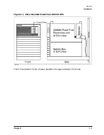
The rear panel of the Electronics Unit and Service Bypass Unit. See
Figure 1-3. The term "rear panel" never refers to the back of the
Battery Box.
Service Bypass Unit
A unit located behind the Electronics Unit that can, when set
properly, isolate the AC input source from the Electronics Unit and
the batteries so that those components can be serviced without
disrupting power to the load.
Service Bypass mode
The condition the UPS is in when AC input power flows directly to
output receptacles and is cut off to the UPS's Electronics Unit and
batteries. The UPS must be in Service Bypass mode (by switching
the Service Bypass switch to
BYPASS
) when its Electronics Unit or
Battery Box needs to be serviced or replaced. Loss of input power
while the UPS is in this mode results in a complete loss of power to
the connected equipment. For more information, refer to “UPS
Modes”.
Sleep mode
The state of the UPS after prolonged disruptions in AC input power
or after it has detected a problem with its internal circuitry. The
UPS may also enter Sleep mode after it has been in Automatic or
Service Bypass mode for more than 30 minutes. In this state, the
UPS uses a minimum of battery power. For more information, about
this mode, refer to “UPS Modes”.
transfer time
The very short time it takes the UPS to go to the on battery state
after the external AC power fails or is removed.
Summary of Contents for PowerTrust A3589A
Page 7: ...Contents Contents 5 ...
Page 8: ...Contents 6 Contents ...
Page 10: ...Contents 8 Figures ...
Page 12: ...Contents 10 Tables ...
Page 14: ...2 ...
Page 20: ...Preface 8 ...
Page 22: ...Preface 10 ...
Page 52: ...1 30 Chapter1 Overview Specifications Figure 1 8 UPS Input Voltage Transfer Points ...
Page 56: ...1 34 Chapter1 Overview UPS Modes Figure 1 10 Simplified UPS 5 5 kVA UPS Block Diagram ...
Page 62: ...1 40 Chapter1 Overview Support Information ...
Page 76: ...2 14 Chapter2 Unpacking and Inspecting Shipping and Storage Requirements ...
Page 104: ...3 28 Chapter3 Installing the UPS Examples of PowerTrust Connections in a System ...
Page 116: ...5 4 Chapter5 Verification Procedures Load Testing ...
Page 148: ...7 6 Chapter7 Cleaning and Maintenance Exchanging Batteries Fan ...
Page 190: ...A 42 AppendixA HP UX UPS Monitor Error Messages Log Only Messages ...
Page 218: ...C 8 AppendixC Configuring the OS for the PowerTrust UPS Power Failing the UPS ...


