Chapter 3
3-11
Installing the UPS
Rackmounting Procedures
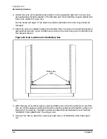
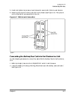
5. Insert and tighten two screws at each bracket to secure both PDUs to each bracket.
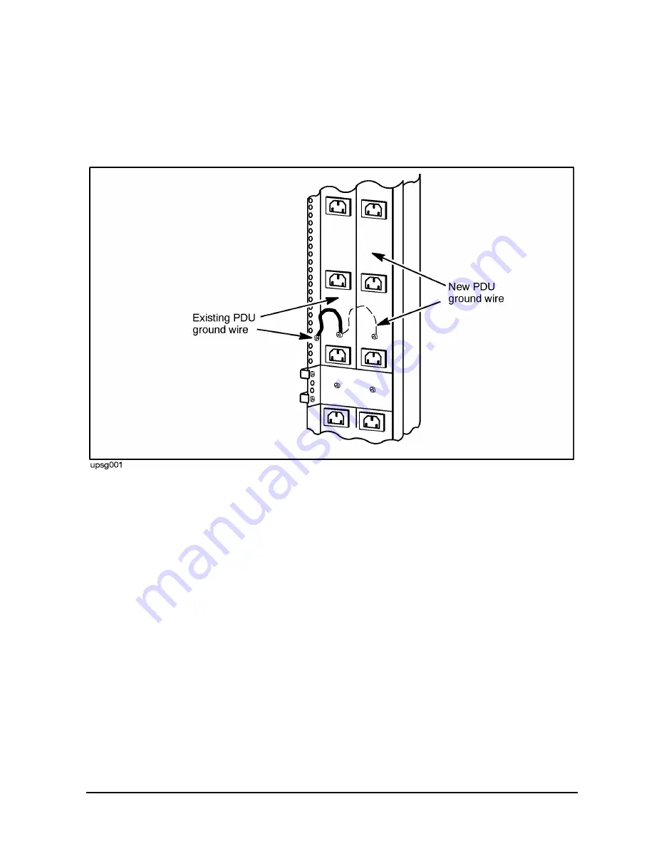
6. Attach a ground wire from the new PDU to the chassis (see Figure 3-7). This ground
wire is required for safe operation of the unit.
Figure 3-7 PDU Ground Connection
Connecting the Battery Box Cable to the Electronics Unit
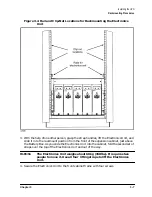
Use the following procedure to connect the cable from the Battery Box to the Electronics
Unit.
1. Before you begin, make sure the UPS/BATTERY switch is set to
DISABLE
.
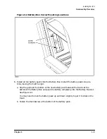
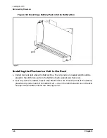
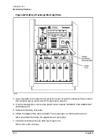
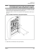
2. Locate the Battery Precharge Shorting Plate that covers the battery cable connector.
See Figure 3-8.
Summary of Contents for PowerTrust A3589A
Page 7: ...Contents Contents 5 ...
Page 8: ...Contents 6 Contents ...
Page 10: ...Contents 8 Figures ...
Page 12: ...Contents 10 Tables ...
Page 14: ...2 ...
Page 20: ...Preface 8 ...
Page 22: ...Preface 10 ...
Page 52: ...1 30 Chapter1 Overview Specifications Figure 1 8 UPS Input Voltage Transfer Points ...
Page 56: ...1 34 Chapter1 Overview UPS Modes Figure 1 10 Simplified UPS 5 5 kVA UPS Block Diagram ...
Page 62: ...1 40 Chapter1 Overview Support Information ...
Page 76: ...2 14 Chapter2 Unpacking and Inspecting Shipping and Storage Requirements ...
Page 104: ...3 28 Chapter3 Installing the UPS Examples of PowerTrust Connections in a System ...
Page 116: ...5 4 Chapter5 Verification Procedures Load Testing ...
Page 148: ...7 6 Chapter7 Cleaning and Maintenance Exchanging Batteries Fan ...
Page 190: ...A 42 AppendixA HP UX UPS Monitor Error Messages Log Only Messages ...
Page 218: ...C 8 AppendixC Configuring the OS for the PowerTrust UPS Power Failing the UPS ...


