h.
Modem module (see
Modem module on page 78
)
i.
Keyboard (see
Keyboard on page 62
)
j.
Top cover (see
Top cover on page 69
)
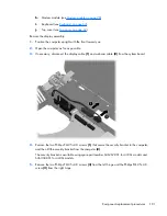
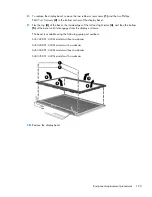
Remove the display assembly:
1.
Position the computer upright with the front toward you.
2.
Open the computer as far as possible.
3.
If necessary, disconnect the display cable
(1)
and webcam cable
(2)
from the system board.
4.
Remove the two Phillips PM2.5×4.0 screws
(1)
that secure the security bracket to the computer,
and then lift the security bracket from the computer
(2)
.
The security bracket is available using spare part number 646367-001 for 4330s models and
646368-001 for 4430s models.
5.
Remove the two Phillips PM2.5×4.0 screws
(3)
from the left hinge and the Phillips PM2.5×4.0
screw
(4)
from the right hinge.
Component replacement procedures
101
Summary of Contents for ProBook 4430s
Page 1: ...HP ProBook 4430s Notebook PC HP ProBook 4330s Notebook PC Maintenance and Service Guide ...
Page 4: ...iv Safety warning notice ...
Page 8: ...viii ...
Page 29: ...Computer major components Computer major components 21 ...
Page 83: ...Cable routing path top Cable routing path bottom Component replacement procedures 75 ...
Page 150: ......

