4.
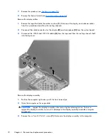
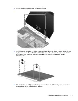
Lift the display assembly up and off the computer
(2)
.
5.
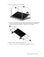
If it is necessary to replace the display bezel, display enclosure, or display hinges, remove the two
mylar screw covers
(1)
and the 2 Torx M2.5×6.0 screws
(2)
that secure the display bezel to the
display assembly. The screw covers are available in the Rubber Kit, spare part number
598678-001.
6.
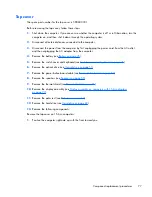
Flex the bottom bezel
(1)
around the hinge areas on the inside of the display enclosure and work
around the periphery of the bezel
(2)
and
(3)
.
Component replacement procedures
73
Summary of Contents for ProBook 4525s - Notebook PC
Page 1: ...HP ProBook 4525s Notebook PC Maintenance and Service Guide ...
Page 4: ...iv Safety warning notice ...
Page 8: ...10 Recycling 131 Battery 131 Display 131 Index 137 viii ...
Page 135: ...RJ 11 modem Pin Signal 1 Unused 2 Tip 3 Ring 4 Unused 5 Unused 6 Unused RJ 11 modem 127 ...
Page 149: ......

