2-4
ProCurve Secure Access 700wl Series Installation and Getting Started Guide
Hardware Installation
Network Uplink Status Indicators
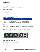
A detailed view of the network interface (uplink port) is shown in Figure 2-4.
Figure 2-4. Network Uplink port
The two LEDs, LED1 and LED2, provide information on the port speed and data connection state of the
default network uplink port as shown in Table 2-2.
Rear Chassis
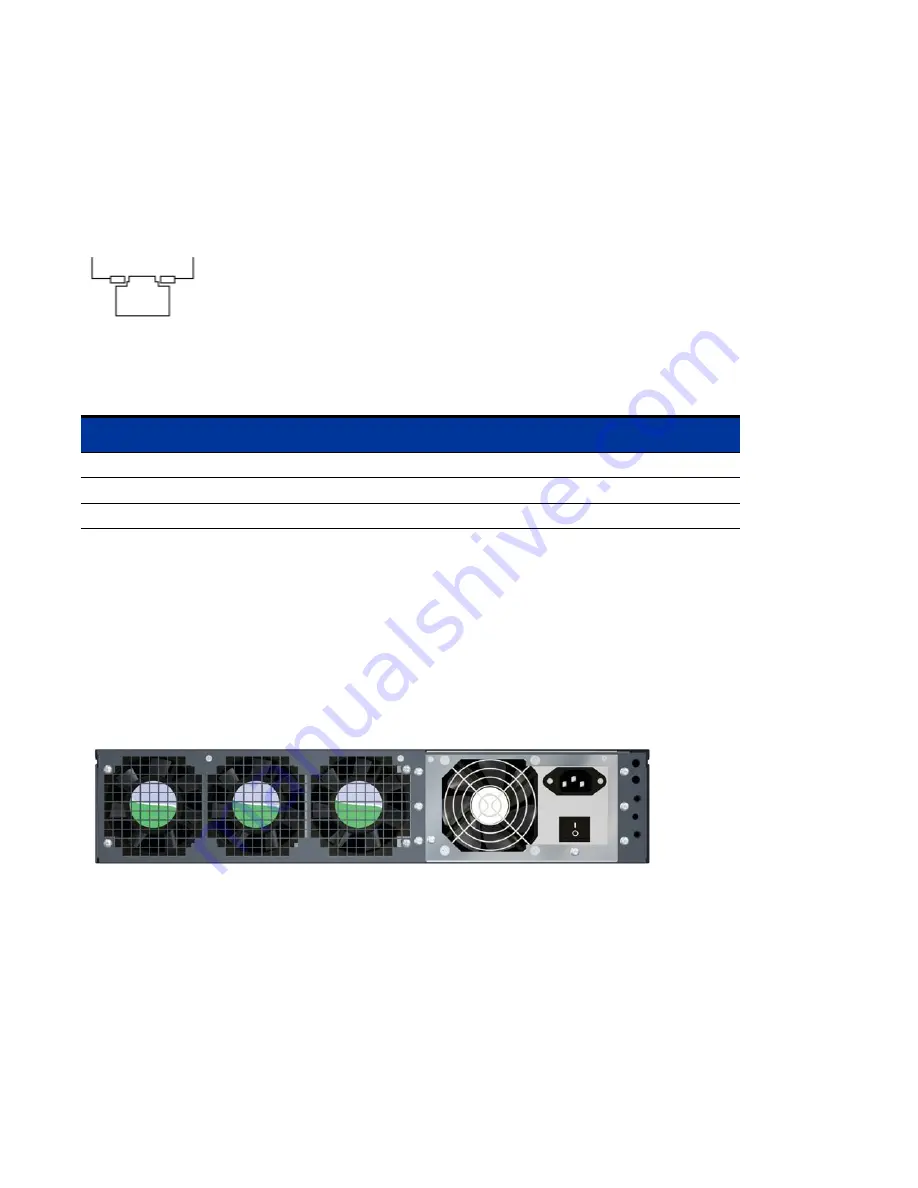
Figure 2-5 shows the rear of the Access Control Server 745wl. There is one control on the rear of the
chassis, a power switch. This switch cannot be used to power on the system. When this switch is in the
Off (0) position, the front panel power button will not function.
Note:
The power switch must be left in the On (I) position for the unit to be operational.
Figure 2-5. Rear chassis of an Access Control Server 745wl
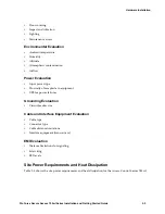
Site Planning Checklist
Before installing an Access Control Server 745wl or XL Access Controller Module, you should evaluate
the items in the following site planning checklist:
Space Evaluation
•
Space and layout
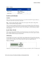
Table 2-2. Network uplink LED status
LED State
LED1 (Port Speed)
LED2 (Connection)
On
Green: 10 Mbps, 1000 Mbps Link
100 Mbps, 1000 Mbps Link
Off
100 Mbps Link and Activity
10 Mbps Link and Activity
Blinking
Green (Blink): 10 Mbps, 1000 Mbps Activity
100 Mbps, 1000 Mbps Link
LED1
LED2
Summary of Contents for ProCurve 745wl
Page 1: ...Installation and Getting Started Guide www procurve com ProCurve Secure Access 700wl Series ...
Page 2: ......
Page 3: ...PROCURVE SECURE ACCESS 700WL SERIES INSTALLATION AND GETTING STARTED GUIDE ...
Page 8: ......
Page 12: ......
Page 24: ......
Page 44: ......
Page 60: ......
Page 66: ......
Page 82: ...E 12 ProCurve Secure Access 700wl Series Installation and Getting Started Guide ...
Page 91: ......


