In
stal
lin
g the
Sw
it
ch
Installing the Switch
Installation Procedures
2-28
610
eps
(
)
Status
A2
B1
B2
A1
Device
Connected
Status
Device
Connected
(
)
RPS
RPS
Pow er
Fault
hp procurve
J8169A
Fan/Temp Status flash = Temperature too high
Fan/Temp Fault flash = Fan failure
Fan/Temp Status
Internal Power Status
In Ready
Out Ready
Backup Power Ports Status
EPS Ports
Pair A
408 W total for PoE applications
EPS Ports: 50V
8.3A max each.
EPS A1
Power
EPS A2
EPS B1
Power
EPS B2
EPS Ports
Pair B
408 W total for PoE applications
100-240 V~ 7.5 A
Line: 50/60 Hz.
50 V
16 A
12 V
7.5 A
100-240 V~ 7.5 A
Line: 50/60 Hz.
50 V
16 A
12 V
7.5 A
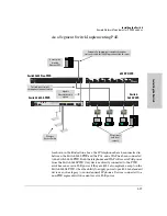
In this example each switch receives 408 watts of PoE power. Each switch is
connected to one port of each pair. If the two switches were connected to both
ports of a pair, both ports of pair A for example, then each switch receives 204
watts. See the following example.
The following illustration demonstrates an example of connectivity between
a 610 EPS device and four Switch devices as a PoE power supply. In this
example each switch receives 204 watts of PoE power.
Summary of Contents for ProCurve Series 2600
Page 2: ......
Page 3: ...ProCurve Series 2600 Switches Installation and Getting Started Guide ...
Page 60: ... This page is intentionally unused ...
Page 82: ... This page is intentionally unused ...
Page 92: ... This page is intentionally unused ...
Page 108: ... This page is intentionally unused ...
Page 115: ......


