background image

HP ProCurve Wireless 170wl 
Radio Card External Antenna 

User’s Guide

Summary of Contents for ProCurve Wireless 170wl

Page 1: ...HP ProCurve Wireless 170wl Radio Card External Antenna User s Guide ...

Page 2: ...urve 802 11g 170wl Card J8431A HP ProCurve 802 11g 170wl Card J8432A Disclaimer HEWLETT PACKARD COMPANY MAKES NO WARRANTY OF ANY KIND WITH REGARD TO THIS MATERIAL INCLUDING BUT NOT LIMITED TO THE IMPLIED WARRANTIES OF MERCHANTABILITY AND FITNESS FOR A PARTICULAR PURPOSE Hewlett Packard shall not be liable for errors contained herein or for incidental or consequential damages in connection with the...

Page 3: ... r e d Only the HP antennas listed in this guide are permitted to be connected to the 170wl radio card You must use the appropriate antennas cables and where applicable surge arrestors for your given region You are responsible for verifying local regulations or legislation that may impose restrictions on the use of specific antenna and cable combinations For this reason HP recom mends that you con...

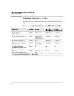
Page 4: ...41A Ceiling or mast 360 Degrees 31 Degrees 7 dBi indoor outdoor directional J8443A Flush wall mount withintegrated articulating feature 65 Degrees 50 Degrees 8 dBi outdoor omnidirectional J8444A Mast 360 Degrees 12 Degrees 11 dBi indoor outdoor wideangle directional J8446A Flush wall mount tilt mount for mast 120 Degrees 13 Degrees MC Card to R SMA cable Thiscablemustbeusedwithallthe above antenna...

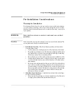
Page 5: ...imum performance mount antennas as high as possible above any obstructions and away from any signal absorbing or reflecting structures such as those containing metal Be sure there are no other radio antennas mounted within 2 m 6 ft Consider the antenna s radio coverage pattern so that it can properly cover the intended service area and not interfere with other radios and antennas Because most ante...

Page 6: ...ecting a location for these antennas For optimum coverage mount the antenna above any obstructions directed at the center of the coverage area sector High gain directional antennas provide a flattened radio coverage pattern in the horizontal plane Use the tilting or articulated mounts to point the antennas towards the coverage area Outdoor Installation When installing an antenna outdoors be sure t...

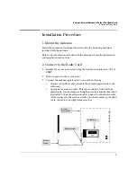
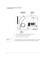
Page 7: ...ing the web browser interface CLI or SNMP 2 Remove power to the access point 3 Connect the antenna pigtail cable to one of the following Adapter cable This cable connects the antenna pigtail cable to the radio card Appropriate extension cable This cable connects to the antenna pigtail cable for an extension of length and or for a required insertion loss table 2 then the extension cable connects to...

Page 8: ...rd 5 Connect the adapter cable to the radio card 6 Reconnect power to the access point Not e Before enabling the radio with an external antenna attached be sure to first configure the access point s antenna mode and transmit power settings Adapter Cable Radio Card Extension Cable Variable Length Antenna Pigtail Access Point 520wl ...

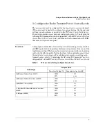
Page 9: ...antenna gain may result in an EIRP equivalent isotropically radiated power power level in excess of the legally imposed limit The transmit power reduction required for each antenna islistedinthe following table Failure toadhereto these guidelines mayviolate the radio laws for your region For additional information on setting radio transmit power refer to Configuring the AP using CLI Commands secti...

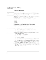
Page 10: ...wser on a network computer Not e The HTTP interface supports the following Web brouser Microsoft Internet Explorer 6 with Service Pack 1 or later Netscape 6 1 or later 2 If necessary disable the Internet proxy settings For Internet Explorer users follow these steps Select Tools Internet Options Click the Connections tab Click LAN Settings If necessary remove the check mark from the Use a proxy ser...

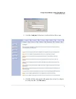
Page 11: ...na with the 170wl Radio Card Installation Procedure 5 Click the Configure button located on the left side of the screen 6 Click the tab that corresponds to the parameter you want to configure For this procedure click Interfaces ...

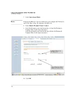
Page 12: ...1bg or 11g the antennas will still work 8 Select Enable Transmit Power Control 9 Select the transmit power level for interface A from the Wireless A Transmit Power Level drop down menu Select the transmit power level for interface B from the Wireless B Transmit Power Level drop down menu 10 Click OK g Operational Mode can be 11b 11bg or 11g TransmitPowerControllimits dropdown menu and setting ...

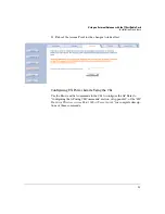
Page 13: ...for the changes to take effect Configuring TX Power Limits Using the CLI Use the Show and Set commands in the CLI to configure the AP Refer to Configuring the AP using CLI Commands section of Appendix C of the HP ProCurve Wireless Access Point 520wl User s Guide for complete descrip tions of these commands ...

Page 14: ...ut notice Copyright Hewlett Packard Company 2004 All rights reserved Reproduction adaptation or translation without prior written permission is prohibited except as allowed under the copyright laws Product of Singapore May 2004 Manual Part Number 5990 6069 5990 6069 ...

Reviews: