
EL-MF877-00 Page 6
Template Revision B
PSG instructions for this template are available at
EL-MF877-01
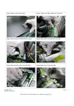
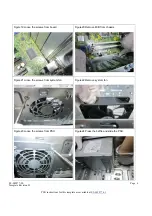
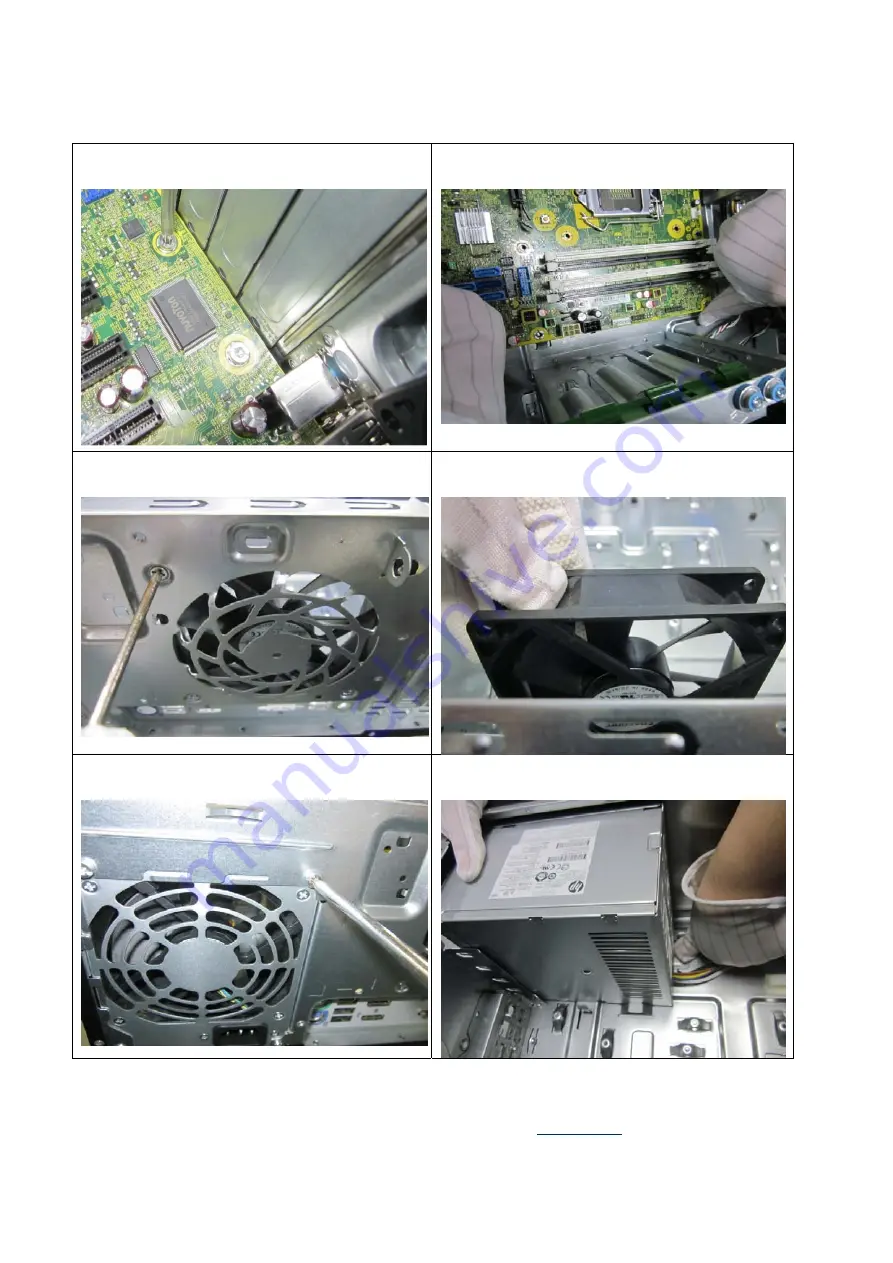
Figure19 Loose the screws from board
Figure20 Remove M/B from chassis
Figure21 Loose the screws from system fan
Figure22 Remove system fan
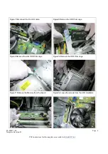
Figure23 Loose the screws from PSU
Figure24 Press the baffle and slide the PSU


