Connectors, Switches, and LEDs
4-6
HP ProLiant DL145 Generation 2 Server Maintenance and Service Guide
Table 4-3: System Board Components
continued
Item
Component Code
Component
36
BT1
3 V internal lithium system battery
37 SW2
System
configuration switch (dip switch)
38
U79
SMSC LPC47M192 Super I/O chipset
39
U60
16 MB DDR SDRAM
40
SW1
NMI (non-maskable interrupt) switch
41
U56
NVIDIA GeForce2 MX400 GPU (Graphics Processor Unit)
42
U82
SMSC LAN91C113I-NC LAN controller (10/100 Mbps)
43
U52
BMC flash EEPROM
44
CN23
BMC debug port
45
U67
QLogic Zircon UL BMC (Baseboard Management Controller)
46
U47
IC61LV25616-10T BMC SRAM
System Switches
The two system switches—SW1 and SW2— are located on the system board.
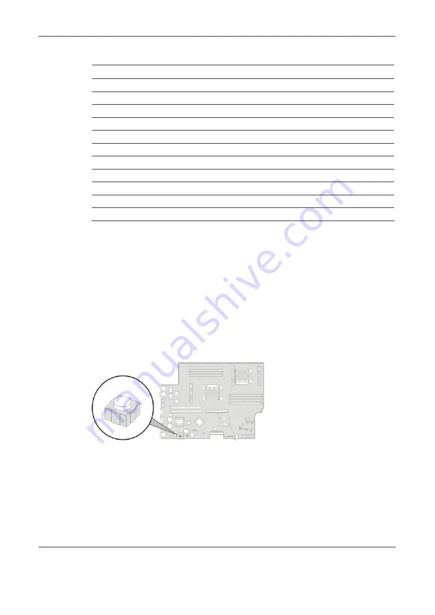
NMI Switch
If the system crashes or stops operating properly, you can use the NMI switch (SW1) to
mechanically force the server to issue a non-maskable interrupt. This will perform a memory
dump—writing the contents of the server's CPU registers and RAM to a network server or to
diskettes. This memory dump can later be analyzed to determine the cause of the problem.
The NMI switch is recessed beneath a small button on the system board. Figure 4-4 show the
location use of this switch. By the default the NMI switch is always enabled.
Figure 4-4: NMI switch
NOTE: Use of the NMI switch is not supported in all NOS. As of the present, NMI implementation is not
available for systems running on Solaris and Linux operating systems.
All manuals and user guides at all-guides.com
all-guides.com


