Removal and replacement procedures 75
10.
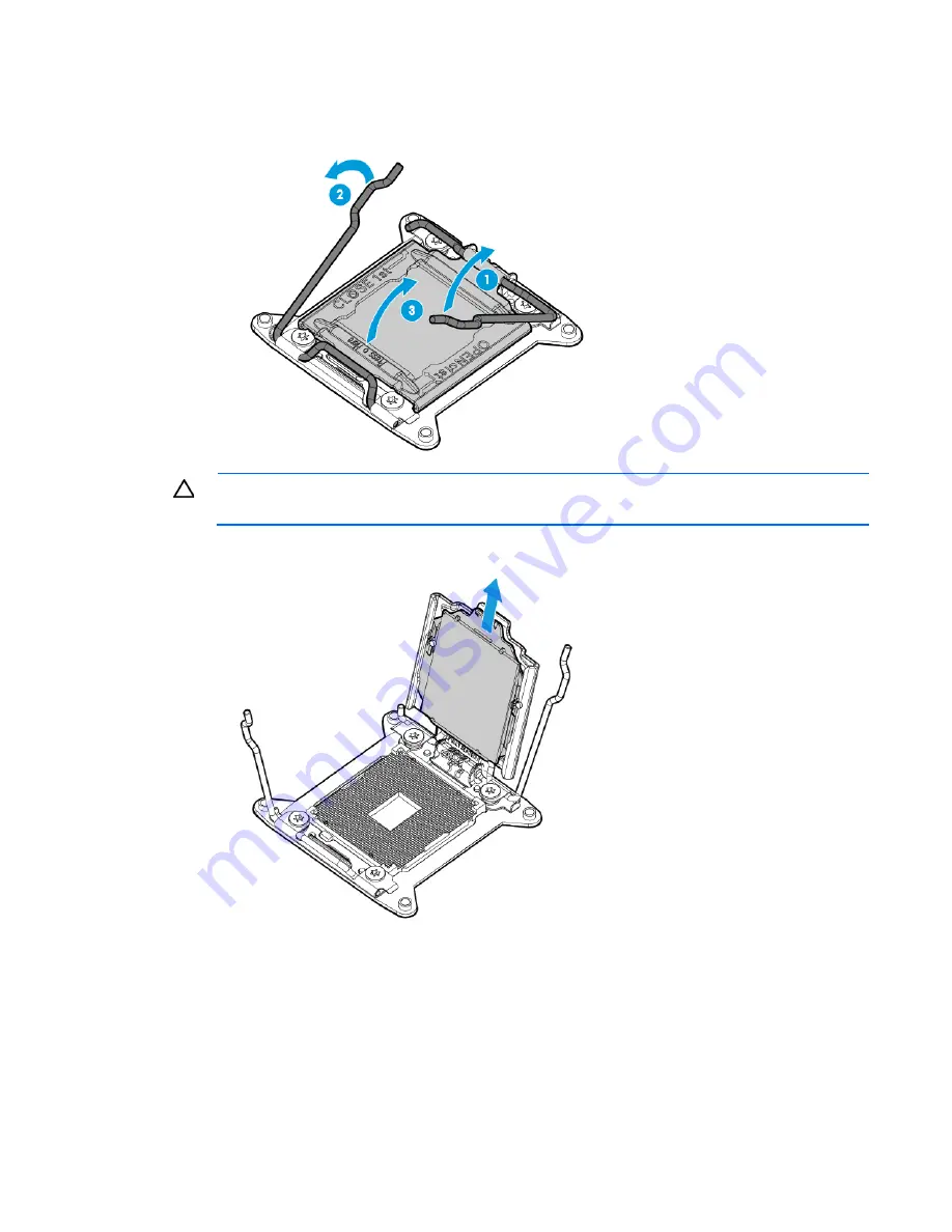
Open each of the processor locking levers in the order indicated, and then open the processor retaining
bracket.
CAUTION:
THE PINS ON THE SYSTEM BOARD ARE VERY FRAGILE AND EASILY DAMAGED.
To
avoid damage to the system board, do not touch the processor or the processor socket contacts.
11.
Remove the processor from the processor retaining bracket.
12.
If installed, remove the dedicated iLO module ("
Dedicated iLO management module
" on page
66
).
13.
Disconnect all cables connected to the system board.
Summary of Contents for ProLiant DL180 Gen9
Page 13: ...Customer self repair 13 ...
Page 14: ...Customer self repair 14 ...
Page 15: ...Customer self repair 15 ...
Page 18: ...Illustrated parts catalog 18 ...
Page 23: ...Illustrated parts catalog 23 ...
Page 121: ...Cabling 121 Item Description 3 USB 3 0 connector cable ...


