background image

30

Customer self repair

Summary of Contents for ProLiant DL360 Gen10

Page 1: ...and maintenance procedures diagnostic tools specifications and requirements for hardware components and software This guide is for an experienced service technician Hewlett Packard Enterprise assumes you are qualified in the servicing of computer equipment trained in recognizing hazards in products and are familiar with weight and stability precautions ...

Page 2: ... Software Computer Software Documentation and Technical Data for Commercial Items are licensed to the U S Government under vendor s standard commercial license Links to third party websites take you outside the Hewlett Packard Enterprise website Hewlett Packard Enterprise has no control over and is not responsible for information outside the Hewlett Packard Enterprise website Acknowledgments Intel...

Page 3: ...embly spare parts 13 Server options 13 Fan spare parts 14 Power supply spare parts 14 Battery spare parts 14 Hot plug drive spare parts 15 Solid state NVMe spare parts 16 Solid state drive uFF M 2 spare parts 17 Solid state drive SAS spare parts 17 Solid state drive SATA spare parts 17 Systems Insight Display spare parts 18 Power switch spare parts 18 Universal Media Bay spare parts 19 Drive black...

Page 4: ...ing and replacing a DIMM 54 Removing and replacing the system battery 55 Removing and replacing the Smart Storage Battery 56 Removing and replacing a processor heatsink assembly 57 Removing and replacing the system board 59 Removing and replacing the LFF optical disk drive display port USB 61 Removing and replacing the SFF optical disk drive display port USB 62 Removing and replacing the LFF power...

Page 5: ... 8 SFF backplane to P408i a controller 98 2 SFF backplane to P816i a controller 98 2 SFF NVMe backplane to primary riser 99 1 SFF rear backplane to system board SATA 99 Additional SFF cabling 99 LFF cables 100 LFF configuration cable routing 100 4 LFF backplane to P408i a controller 100 Additional LFF cabling 100 Specifications 101 Environmental specifications 101 Server specifications 101 Power s...

Page 6: ... resources 110 Accessing Hewlett Packard Enterprise Support 110 Accessing updates 110 Customer self repair 110 Remote support 111 Warranty information 111 Regulatory information 112 Documentation feedback 112 6 Contents ...

Page 7: ...e riser cage spare part on page 7 3 PCIe riser blank spare parts on page 8 4 Miscellaneous blank spare parts on page 8 5 Server ear and front bezel spare parts on page 8 6 Rack mounting hardware spare parts on page 8 7 Cable management arm spare parts on page 8 Not shown Access panel spare parts Customer self repair on page 110 mandatory Description Spare part number Access panel 875536 001 PCIe r...

Page 8: ...ry Description Spare part number Miscellaneous blanks kit 775423 001 Server ear and front bezel spare parts Customer self repair on page 110 mandatory Description Spare part number Left ear 875541 001 Right ear 875542 001 1U Bezel 875561 001 Rack mounting hardware spare parts Customer self repair on page 110 mandatory Description Spare part number SFF Easy Install Rail kit 875544 001 LFF Easy Inst...

Page 9: ...sink spare parts on page 9 2 Processor spare parts on page 9 3 DIMM spare parts on page 11 4 Smart Array controller spare parts on page 11 5 PCIe riser board spare parts on page 12 6 FlexibleLOM adapter spare parts on page 13 7 System board assembly spare parts on page 13 Heatsink spare parts Customer self repair on page 110 No Description Spare part number Standard heatsink 872452 001 Performance...

Page 10: ...875722 001 3 2GHz Intel Xeon G 6134 processor 130W 875723 001 3 2GHz Intel Xeon G 6134M processor 130W 878083 001 3 0GHz Intel Xeon G 6136 processor 150W 875724 001 2 0GHz Intel Xeon G 6138 processor 125W 874735 001 2 3GHz Intel Xeon G 6140 processor 140W 874734 001 2 3GHz Intel Xeon G 6140M processor 140W 878084 001 2 6GHz Intel Xeon G 6142 processor 150W 874733 001 2 6GHz Intel Xeon G 6142M proc...

Page 11: ...6V R 850880 001 16GB 1Gx8 PC4 2666V R 868846 001 32GB 2Gx4 PC4 2666V R 850881 001 64GB 2Gx4 PC4 2666V L 850882 001 Controller spare parts Smart Array controller spare parts Customer self repair on page 110 mandatory Description Spare part number HPE Smart Array E208i a Controller 836259 001 HPE Smart Array E208i a LH Controller 871039 001 HPE Smart Array P408i a Controller 836260 001 HPE Smart Arr...

Page 12: ...eFabric 84Q 4p 8Gb FC HBA 853009 001 HPE SN1100Q 16Gb 1p FC HBA 863010 001 HPE SN1100Q 16Gb 2p FC HBA 853011 001 Converged network adapter spare parts Customer self repair on page 21 mandatory Description Spare part number HPE CN1100R 2P Converged Network Adapter 706801 001 HPE StoreFabric CN1100R T 10Gb Converged Network Adapter 872605 001 HPE StoreFabric CN1200E 10Gb Converged Network Adapter 76...

Page 13: ...2 port 544 QSFP Adapter 764736 001 System board assembly spare parts Customer self repair on page 110 optional Description Spare part number System board assembly 875552 001 Server options Hewlett Packard Enterprise continually improves and changes product parts For complete and current supported parts information see the Hewlett Packard Enterprise PartSurfer website Item Description 1 Fan spare p...

Page 14: ...spare parts Customer self repair on page 110 mandatory Description Spare part number Standard fans 875283 001 High performance fans 875284 001 Power supply spare parts Customer self repair on page 110 mandatory Description Spare part number 800W Flex slot 277VDC 866727 001 800W Flex slot 48VDC 866728 001 500W Flex slot Platinum 866729 001 800W Flex slot Platinum 866730 001 800W Flex slot High Effi...

Page 15: ...862129 001 3TB SAS 7 2K LFF SC DS HDD 846614 001 4TB SAS 7 2K LFF SC 512e DS HDD 862141 001 4TB SAS 12G 7 2K LFF SC DS HDD 872745 001 4TB SAS 7 2K LFF SC HDD 819079 001 4TB SATA 7 2K 6G LFF SC DS HDD 872772 001 4TB SATA 7 2K LFF SC HDD 862127 001 4TB SATA 7 2K LFF SC 512e DS HDD 862139 001 6TB SATA 7 2K LFF SC DS HDD 846608 001 6TB SATA 7 2K LFF SC 512e DS HDD 862138 001 6TB SAS 7 2K LFF SC 512e D...

Page 16: ... 001 600GB SAS 15K SFF SC HDD 759548 001 600GB SAS 15K SFF SC 512e HDD 748435 001 900GB SAS 15K SFF SC DS HDD 870795 001 900GB SAS 15K SFF SC 512e DS HDD 870798 001 Solid state NVMe spare parts Customer self repair on page 21 mandatory Description Spare part number 400GB NVMe x4 WI SFF SC SSD 765059 001 400GB NVMe x4 RI SFF SCN SSD 765067 001 400GB NVMe x4 MU SFF SCN SSD 765063 001 800GB NVMe x4 W...

Page 17: ...9 001 1 6TB SAS MU SFF SC SSD 822788 001 1 92TB SAS RI SFF SC SSD 817051 001 3 2TB SAS MU SFF SC SSD 822790 001 3 84TB SAS RI SFF SC SSD 817053 001 Solid state drive SATA spare parts Customer self repair on page 21 mandatory Description Spare part number 150GB SATA 6G RI SFF SC DS SSD 869575 001 200GB SATA WI SFF SC SSD 805385 001 200GB SATA WI LFF SCC SSD 805386 001 240GB SATA 6G RI SFF SC DS SSD...

Page 18: ...SSD 805391 001 1 2TB SATA WI LFF SCC SSD 805392 001 1 6TB SATA 6G WI SFF SC DS SSD 872516 001 1 6TB SATA 6G WI LFF SCC DS SSD 872517 001 1 6TB SATA 6G RI SFF SC DS SSD 869581 001 1 6TB SATA 6G RI LFF SCC DS SSD 869582 001 1 92TB SATA 6G RI SFF SC DS SSD 868930 001 1 92TB SATA 6G MU SFF SC DS SSD 872522 001 3 84TB SATA 6G RI SFF SC DS SSD 868932 001 Systems Insight Display spare parts Customer self...

Page 19: ...ne 875556 001 2SFF Dual port drive backplane 875557 001 1SFF rear drive backplane plus cage assembly 875558 001 4LFF drive backplane 775402 001 8SFF drive backplane 780428 001 Cable kit spare parts Customer self repair on page 110 mandatory Description Spare part number 2SFF 8SFF cables kit 875566 001 10SFF cables kit 875567 001 4LFF backplane power cable 875568 001 1SFF rear backplane SATA 875569...

Page 20: ...umber HPE Trusted Platform Module Gen 10 TAA 872159 001 Thermal grease spare parts Customer self repair on page 21 no Description Spare part number 2 0g thermal grease 1g per processor 777298 001 20 Thermal grease spare parts ...

Page 21: ... within a defined period of time normally five 5 business days The defective part must be returned with the associated documentation in the provided shipping material Failure to return the defective part may result in Hewlett Packard Enterprise billing you for the replacement With a customer self repair Hewlett Packard Enterprise will pay all shipping and part return costs and determine the courie...

Page 22: ... Packard Enterprise sono realizzati con numerosi componenti che possono essere riparati direttamente dal cliente CSR Customer Self Repair Se in fase di diagnostica Hewlett Packard Enterprise o un centro di servizi o di assistenza Hewlett Packard Enterprise identifica il guasto come riparabile mediante un ricambio CSR Hewlett Packard Enterprise lo spedirà direttamente al cliente per la sostituzione...

Page 23: ...en muss das Teil von einem Hewlett Packard Enterprise Servicepartner ersetzt werden Im illustrierten Teilekatalog sind diese Teile mit No bzw Nein gekennzeichnet CSR Teile werden abhängig von der Verfügbarkeit und vom Lieferziel am folgenden Geschäftstag geliefert Für bestimmte Standorte ist eine Lieferung am selben Tag oder innerhalb von vier Stunden gegen einen Aufpreis verfügbar Wenn Sie Hilfe ...

Page 24: ...entes CSR Hewlett Packard Enterprise especificará si los componentes defectuosos deberán devolverse a Hewlett Packard Enterprise En aquellos casos en los que sea necesario devolver algún componente a Hewlett Packard Enterprise deberá hacerlo en el periodo de tiempo especificado normalmente cinco días laborables Los componentes defectuosos deberán devolverse con toda la documentación relacionada y ...

Page 25: ...eretourneerde onderdeel en kiest Hewlett Packard Enterprise zelf welke koerier transportonderneming hiervoor wordt gebruikt Neem contact op met een Service Partner voor meer informatie over het Customer Self Repair programma van Hewlett Packard Enterprise Informatie over Service Partners vindt u op de Hewlett Packard Enterprise website Garantieservice Parts Only Het is mogelijk dat de Hewlett Pack...

Page 26: ...o correspondente no material de transporte fornecido Caso não o faça a Hewlett Packard Enterprise poderá cobrar a reposição Para as peças de reparo feito pelo cliente a Hewlett Packard Enterprise paga todas as despesas de transporte e de devolução da peça e determina a transportadora serviço postal a ser utilizado Para obter mais informações sobre o programa de reparo feito pelo cliente da Hewlett...

Page 27: ...Customer self repair 27 ...

Page 28: ...28 Customer self repair ...

Page 29: ...Customer self repair 29 ...

Page 30: ...30 Customer self repair ...

Page 31: ...Wrist straps are flexible straps with a minimum of 1 megohm 10 percent resistance in the ground cords To provide proper ground wear the strap snug against the skin Use heel straps toe straps or boot straps at standing workstations Wear the straps on both feet when standing on conductive floors or dissipating floor mats Use conductive field service tools Use a portable field service kit with a fold...

Page 32: ...be sure that The leveling jacks are extended to the floor The full weight of the rack rests on the leveling jacks The stabilizing feet are attached to the rack if it is a single rack installation The racks are coupled together in multiple rack installations Only one component is extended at a time A rack may become unstable if more than one component is extended for any reason WARNING To reduce th...

Page 33: ...e This method forces the server to enter standby mode without properly exiting applications and the OS If an application stops responding you can use this method to force a shutdown Use a virtual power button selection through iLO This method initiates a controlled remote shutdown of applications and the OS before the server enters standby mode Before proceeding verify that the server is in standb...

Page 34: ...the rack For more information see the documentation that ships with the rack mounting option 4 Place the server on a sturdy level surface Remove the access panel WARNING To reduce the risk of personal injury from hot surfaces allow the drives and the internal system components to cool before touching them CAUTION Do not operate the server for long periods with the access panel open or removed Oper...

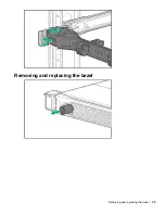
Page 35: ...Removing and replacing the bezel Removing and replacing the bezel 35 ...

Page 36: ...s indicated Removing a SAS SATA drive Procedure 1 Back up all server data 2 Observe the LED status of the drive and determine if it can be removed 3 Remove the drive To replace the component reverse the removal procedure 36 Removing the hard drive blank ...

Page 37: ...g stops and the Do Not Remove button is no longer illuminated c Push the Do Not Remove button and then remove the drive Removing and replacing an M 2 SSD This procedure is for drives on the system board riser or expansion card Do not use this procedure on uFF drives Procedure 1 Power down the server 2 Remove all power a Disconnect each power cord from the power source b Disconnect each power cord ...

Page 38: ...val procedure Removing and replacing a uFF drive Procedure 1 Back up all server data 2 Observe the LED status of the drive and determine if it can be removed 3 Remove the drive To remove the drive carrier 38 Removing and replacing a uFF drive ...

Page 39: ...d with either a component or a blank Procedure 1 Power down the server Powering down the server on page 33 2 Remove all power a Disconnect each power cord from the power source b Disconnect each power cord from the server 3 Access the product rear panel Releasing the cable management arm on page 34 4 Remove the power supply WARNING To reduce the risk of personal injury from hot surfaces allow the ...

Page 40: ...mproper cooling that can lead to thermal damage IMPORTANT For optimum cooling install fans in all primary fan locations Procedure 1 Extend the server from the rack on page 33 2 Remove the access panel 3 Remove the fan IMPORTANT When a hot plug fan is removed the other fans in the server will increase speed to compensate CAUTION To avoid server shutdown a fan must be replaced within 60 seconds of b...

Page 41: ...e access panel open or removed Operating the server in this manner results in improper airflow and improper cooling that can lead to thermal damage IMPORTANT For optimum cooling install fans in all primary fan locations Procedure 1 Extend the server from the rack 2 Remove the access panel 3 Remove the fan blank Removing and replacing a fan blank 41 ...

Page 42: ...nstalling the PCI riser cage Procedure 1 Power down the server 2 Remove all power a Disconnect each power cord from the power source b Disconnect each power cord from the server 3 Do one of the following a Extend the server from the rack b Remove the server from the rack 4 Remove the access panel 5 Remove the riser cage 6 Remove the riser blank To remove blanks from the primary riser 42 Removing a...

Page 43: ...To remove blanks from the secondary riser a Lift the rear wall latch Half height b Remove the riser blank Removal and replacement procedures 43 ...

Page 44: ...rver or expansion boards power down the server and remove all AC power cords before removing or installing the PCI riser cage Procedure 1 Power down the server 2 Remove all power a Disconnect each power cord from the power source b Disconnect each power cord from the server 3 Do one of the following 44 Removing and replacing a riser cage ...

Page 45: ... Remove the access panel 5 Remove the riser cage To remove the primary riser cage To remove the secondary riser cage a Remove the primary riser cage b Open the secondary rear wall c Remove any expansion boards d Remove the riser cage Removal and replacement procedures 45 ...

Page 46: ...power cords before removing or installing the PCI riser cage Procedure 1 Power down the server 2 Remove all power a Disconnect each power cord from the power source b Disconnect each power cord from the server 3 Do one of the following a Extend the server from the rack b Remove the server from the rack 4 Remove the access panel 5 Remove the riser cage 46 Removing and replacing a primary riser card...

Page 47: ...age To replace the component reverse the removal procedure Removing and replacing an expansion board Procedure 1 Power down the server 2 Remove all power a Disconnect each power cord from the power source b Disconnect each power cord from the server Removing and replacing an expansion board 47 ...

Page 48: ...rd from the secondary riser a Remove the primary riser cage b Lift the secondary rear wall c Remove the expansion card To replace the component reverse the removal procedure Removing and replacing the intrusion detection switch Procedure 1 Power down the server 2 Remove all power a Disconnect each power cord from the power source b Disconnect each power cord from the server 3 Do one of the followi...

Page 49: ...intrusion detection switch Procedure 1 Power down the server 2 Remove all power a Disconnect each power cord from the power source b Disconnect each power cord from the server 3 Do one of the following a Extend the server from the rack b Remove the server from the rack 4 Remove the access panel 5 Disconnect the cable and remove the switch Removing and replacing the intrusion detection switch 49 ...

Page 50: ...mponents to cool before touching them 2 Power down the server 3 Remove all power a Disconnect each power cord from the power source b Disconnect each power cord from the server 4 Do one of the following a Extend the server from the rack b Remove the server from the rack 5 Remove the access panel 6 Remove the riser cage 7 If needed disconnect the GPU power cable and then remove the GPU from the ris...

Page 51: ...If there is no power cable remove the GPU 8 If replacing the system board remove the GPU support bracket Removal and replacement procedures 51 ...

Page 52: ...al system components to cool before touching them 2 Power down the server 3 Remove all power a Disconnect each power cord from the power source b Disconnect each power cord from the server 4 Do one of the following a Extend the server from the rack b Remove the server from the rack 5 Remove the access panel 6 Remove the primary riser cage 7 Disconnect the GPU power cable from the riser and then re...

Page 53: ...Disconnect each power cord from the power source b Disconnect each power cord from the server 3 Disconnect the LAN segment cables 4 Do one of the following Extend the server from the rack Remove the server from the rack 5 Remove the FlexibleLOM To replace the component reverse the removal procedure Removing and replacing the FlexibleLOM 53 ...

Page 54: ...ing the cables 6 Remove the controller To replace the component reverse the removal procedure Removing and replacing a DIMM To identify DIMMs installed in the server see DIMM slot locations Prerequisites Before replacing memory read the memory configuration and population guidelines in the server user guide Procedure 1 Power down the server 2 Remove all power a Disconnect each power cord from the ...

Page 55: ...arge the battery Do not expose the battery to temperatures higher than 60 C 140 F Do not disassemble crush puncture short external contacts or dispose of in fire or water Replace only with the spare designated for this product Procedure 1 Power down the server Powering down the server on page 33 2 Remove all power Disconnect each power cord from the power source Disconnect each power cord from the...

Page 56: ...der Removing and replacing the Smart Storage Battery Procedure 1 Power down the server 2 Remove all power a Disconnect each power cord from the power source b Disconnect each power cord from the server 3 Do one of the following a Extend the server from the rack b Remove the server from the rack 4 Remove the access panel 5 Disconnect the cable and then remove the battery 56 Removing and replacing t...

Page 57: ...ent reverse the removal procedure Removing and replacing a processor heatsink assembly Procedure 1 Observe the following alerts CAUTION To avoid damage to the processor or system board only authorized personnel should attempt to replace or install the processor in this server Removing and replacing a processor heatsink assembly 57 ...

Page 58: ...ts CAUTION When handling the heatsink always hold it along the top and bottom of the fins Holding it from the sides can damage the fins CAUTION Observe the label on the heatsink Tightening or loosening the screws in the wrong order can damage the heatsink 2 Power down the server 3 Remove all power a Disconnect each power cord from the power source b Disconnect each power cord from the server 4 Do ...

Page 59: ... one of the following a Extend the server from the rack b Remove the server from the rack 4 Remove all power supplies 5 Remove the access panel 6 Take note of port numbers and cables connections to risers and the system board 7 Disconnect and remove all cables that are connected to risers or the system board 8 Remove all riser cages 9 Remove the GPU support bracket 10 Remove the controller 11 Remo...

Page 60: ...n press the Enter key 3 Enter the serial number and press the Enter key The following message appears The serial number should only be modified by qualified service personnel This value should always match the serial number located on the chassis 4 To clear the warning press the Enter key 5 Enter the serial number and press the Enter key 6 Select Product ID The following warning appears Warning Th...

Page 61: ...isconnect each power cord from the server 3 Do one of the following a Extend the server from the rack b Remove the server from the rack 4 Remove the access panel 5 Disconnect the optical drive cable from the system board 6 Disconnect the display port USB cable from the system board 7 Remove the component Removing and replacing the LFF optical disk drive display port USB 61 ...

Page 62: ...and replacing the SFF optical disk drive display port USB Procedure 1 Power down the server 2 Remove all power a Disconnect each power cord from the power source b Disconnect each power cord from the server 3 Do one of the following 62 Removing and replacing the SFF optical disk drive display port USB ...

Page 63: ...he server from the rack 4 Remove the access panel 5 If needed disconnect the optical disk drive cable from the system board 6 Disconnect the display port USB cable from the system board 7 Remove the component Removal and replacement procedures 63 ...

Page 64: ...all power a Disconnect each power cord from the power source b Disconnect each power cord from the server 3 Do one of the following a Extend the server from the rack b Remove the server from the rack 4 Remove the access panel 5 Disconnect the cable from the system board 6 Remove the power module 64 Removing and replacing the LFF power switch module ...

Page 65: ...ver 2 Remove all power a Disconnect each power cord from the power source b Disconnect each power cord from the server 3 Do one of the following a Extend the server from the rack b Remove the server from the rack 4 Remove the access panel 5 Disconnect the cable from the system board Removing and replacing the Systems Insight Display power module 65 ...

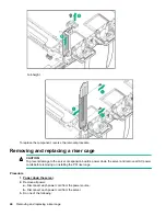
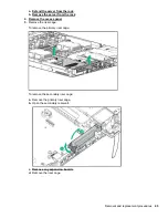
Page 66: ...6 Remove the component SFF LFF 66 Removal and replacement procedures ...

Page 67: ...r source b Disconnect each power cord from the server 3 Do one of the following a Extend the server from the rack b Remove the server from the rack 4 Remove the access panel 5 Remove the drive or drive blank from the drive cage 6 Disconnect all cables from the drive backplane 7 Remove the drive cage 8 Remove the slot 2 bracket from the riser cage Removing and replacing the rear SFF drive cage 67 ...

Page 68: ...cage 10 Remove the riser from the riser cage To replace the component reverse the removal procedure Removing and replacing the 2SFF drive cage Procedure 1 Power down the server 2 Remove all power 68 Removing and replacing the 2SFF drive cage ...

Page 69: ...ace the component reverse the removal procedure Removing and replacing the 4LFF drive backplane Procedure 1 Power down the server 2 Remove all power a Disconnect each power cord from the power source b Disconnect each power cord from the server 3 Do one of the following a Extend the server from the rack b Remove the server from the rack 4 Remove the access panel 5 Remove all drives and drive blank...

Page 70: ...the power source b Disconnect each power cord from the server 3 Do one of the following a Extend the server from the rack b Remove the server from the rack 4 Remove the access panel 5 Remove all drives and drive blanks Note where each drive is located 6 Disconnect and remove all cables from the drive backplane 7 Remove the drive backplane 70 Removing and replacing the 8SFF drive backplane ...

Page 71: ...lation Improper grounding can cause electrostatic discharge Procedure 1 Back up all server data 2 Power down the server 3 Do one of the following Extend the server from the rack Remove the server from the rack 4 Remove the access panel 5 Remove all drives and drive blanks Note where each drive is located 6 Disconnect all cables from the drive backplane 7 Remove the drive backplane Removing and rep...

Page 72: ...TION If the TPM is removed from the original server and powered up on a different server data stored in the TPM including keys will be erased If you suspect a TPM board failure leave the TPM installed and remove the system board Contact a Hewlett Packard Enterprise authorized service provider for a replacement system board and TPM board 72 HPE Trusted Platform Module 2 0 Gen10 Option ...

Page 73: ...ntenance Error Message Guide for HPE ProLiant Gen10 servers and HPE Synergy provides a list of error messages and information to assist with interpreting and resolving error messages Integrated Management Log Messages and Troubleshooting Guide for HPE ProLiant Gen 10 and HPE Synergy provides IML messages and associated troubleshooting information to resolve critical and cautionary IML events To ac...

Page 74: ...oftware collaborate to enhance platform security UEFI Graphical User Interface GUI An Embedded UEFI Shell that provides a preboot environment for running scripts and tools Boot support for option cards that only support a UEFI option ROM Selecting the boot mode This server provides two Boot Mode configurations UEFI Mode and Legacy BIOS Mode Certain boot options require that you select a specific b...

Page 75: ...ww hpe com info ProLiantUEFI docs You can customize the certificates embedded in the UEFI BIOS by adding or removing your own certificates either from a management console directly attached to the server or by remotely connecting to the server using the iLO Remote Console You can configure Secure Boot Using the System Utilities options described in the following sections The RESTful API For more i...

Page 76: ...additional components You can also update any components that have been outdated since the server was manufactured Intelligent Provisioning operation Intelligent Provisioning includes the following components Critical boot drivers Active Health System AHS Erase Utility Deployment Settings IMPORTANT Although your server is pre loaded with firmware and drivers you should update the firmware upon ini...

Page 77: ...3 0 ports can be used with all devices in Legacy BIOS Boot Mode but are not available at USB 3 0 speeds in the preboot environment Standard USB support USB support from within the operating system is provided by the OS through the appropriate USB device drivers Support for USB 3 0 varies by operating system For maximum compatibility of USB 3 0 devices with all operating systems Hewlett Packard Ent...

Page 78: ...res an administrator to download the HPE SSA executables and install them You can run HPE SSA online after launching the host operating system For more information see HPE Smart Array SR Gen10 Configuration Guide at the Hewlett Packard Enterprise website Array Configuration Utility ACU is a utility with the following features Runs as a local application or remote service accessed through the HPE S...

Page 79: ...ge Administrator User Guide on the Hewlett Packard Enterprise website Automatic Server Recovery ASR is a feature that causes the system to restart when a catastrophic operating system error occurs such as a blue screen ABEND does not apply to HPE ProLiant DL980 Servers or panic A system fail safe timer the ASR timer starts when the System Management driver also known as the Health Driver is loaded...

Page 80: ... drive optional 4 USB 2 0 port optional 5 USB 3 0 port 6 iLO Service Port The operating system does not recognize this port as a USB port 7 SAS SATA drive bays 4 LFF Item Description 1 Optical drive blank optional 2 Serial label pull tab 3 Display port optional 4 USB 2 0 port optional Table Continued 80 Component identification ...

Page 81: ...AS SATA drive bays 10 SFF NVMe SAS Combo Item Description 1 Serial label pull tab 2 Systems Insight Display optional 3 USB 3 0 port 4 SAS SATA NVMe drive bays NVMe drives must be used in bays 9 and 10 SAS SATA drives are not supported in those bays Front panel LEDs and buttons 8SFF 10SFF Front panel LEDs and buttons 81 ...

Page 82: ...id green Normal Flashing green iLO is rebooting Flashing amber System degraded Flashing red System critical 4 NIC status LED Solid green Link to network Flashing green Network active Off No network activity When all four LEDs described in this table flash simultaneously a power fault has occurred Facility power is not present power cord is not attached no power supplies are installed power supply ...

Page 83: ...Solid green Normal Flashing green iLO is rebooting Flashing amber System degraded Flashing red System critical 4 Power On Standby button and system power LED Solid green System on Flashing green Performing power on sequence Solid amber System in standby Off No power present When all four LEDs described in this table flash simultaneously a power fault has occurred To identify components in a degrad...

Page 84: ...g table provides a list of power fault LEDs and the subsystems that are affected Not all power faults are used by all servers Subsystem LED behavior System board 1 flash Processor 2 flashes Memory 3 flashes Riser board PCIe slots 4 flashes FlexibleLOM 5 flashes Removable HPE Flexible Smart Array controller Smart SAS HBA controller 6 flashes System board PCIe slots 7 flashes Power backplane or stor...

Page 85: ...ge Over temp LED Off Normal Amber High system temperature detected Amp Status LED Off AMP modes disabled Solid green AMP mode enabled Solid amber Failover Flashing amber Invalid configuration Power cap LED Off System is in standby or no cap is set Solid green Power cap applied When the health LED on the front panel illuminates either amber or red the server is experiencing a health event For more ...

Page 86: ...The server has detected a hardware critical temperature level PCI riser amber Red Green The PCI riser cage is not seated properly Fan amber Amber Green One fan has failed or has been removed Fan amber Red Green Two or more fans have failed or been removed Power supply amber Red Amber One or more of the following conditions may exist Only one power supply is installed and that power supply is in st...

Page 87: ...her troubleshooting is required Test each bank of DIMMs by removing all other DIMMs Isolate the failed DIMM by replacing each DIMM in a bank with a known working DIMM Rear panel components Item Description 1 Slot 1 PCIe3 2 Slot 2 PCIe3 3 Slot 3 PCIe3 optional requires second processor 4 Power supply 2 PS2 5 Power supply 1 PS1 6 Video port 7 NIC port 4 8 NIC port 3 9 NIC port 2 10 NIC port 1 11 iLO...

Page 88: ... 2L iLO 5 standard NIC link LED Solid green Link exists Off No link exists 3 Power supply 2 LED Solid green Normal Off One or more of the following conditions exists AC power unavailable Power supply failed Power supply in standby mode Power supply exceeded current limit 4 Power supply 1 LED Solid green Normal Off One or more of the following conditions exists AC power unavailable Power supply fai...

Page 89: ... 3 8 x1 SATA port 4 9 Front power USB 3 0 connector 10 Optical SATA port 5 11 Smart Storage Battery connector 12 Micro SD card slot 13 Chassis Intrusion Detection connector 14 Drive backplane power connector 15 Dual internal USB 3 0 connector 16 Type a SmartArray connector 17 Secondary processor 2 PCIe riser connector 18 System battery 19 TPM connector optional 20 Serial port connector optional Sy...

Page 90: ... some configurations cannot be restored For more information see Secure Boot configuration NMI functionality An NMI crash dump enables administrators to create crash dump files when a system is hung and not responding to traditional debugging methods An analysis of the crash dump log is an essential part of diagnosing reliability problems such as hanging operating systems device drivers and applic...

Page 91: ...1 through 12 for each processor The supported AMP modes use the letter assignments for population guidelines Device numbers 8SFF device bay numbering 8SFF 2 SFF device bay numbering Item Description 1 Box 1 bays 1 8 2 Box 2 bays 1 and 2 DIMM slot locations 91 ...

Page 92: ...d 10 The other bays support a mix of NVMe and SAS drives Optional rear device bay numbering The optional rear device bay supports either 1 SFF drive in a SmartDrive carrier or 2 uFF M 2 drives in an HPE Smart Carrier M 2 SCM When the HPE SFF Flash Adapter is installed the uFF drives are recognized as 1 and 101 Hot plug drive LED definitions 92 Hot plug drive LED definitions ...

Page 93: ...pansion or logical drive extension or is erasing Flashing amber green The drive is a member of one or more logical drives and predicts the drive will fail Flashing amber The drive is not configured and predicts the drive will fail Solid amber The drive has failed Off The drive is not configured by a RAID controller NVMe SSD components The NVMe SSD is a PCIe bus device A device attached to a PCIe b...

Page 94: ...host application Flashing blue The drive firmware is being updated or requires an update 2 uFF drive ejection latch Removes the uFF drive when released 3 Do not remove LED Off OK to remove the drive Removing the drive does not cause a logical drive to fail Solid white Do not remove the drive Removing the drive causes one or more of the logical drives to fail Table Continued 94 uFF drive components...

Page 95: ...handle Removes the SFF flash adapter when released Hot plug fans CAUTION To avoid damage to server components fan blanks must be installed in fan bays 1 and 2 in a single processor configuration CAUTION To avoid damage to the equipment do not operate the server for extended periods of time if the server does not have the optimal number of fans installed Although the server might boot Hewlett Packa...

Page 96: ...cool the server The server shuts down during the following temperature related scenarios At POST and in the OS iLO performs an orderly shutdown if a cautionary temperature level is detected If the server hardware detects a critical temperature level before an orderly shutdown occurs the server performs an immediate shutdown When the Thermal Shutdown feature is disabled in the BIOS Platform Configu...

Page 97: ...1 874615 001 8 SFF SAS SATA Backplane Type p Smart Array Controller Slot 2 2 SFF Backplane Option Kit 876867 001 2 SFF SAS SATA Backplane Embedded SATA Type p Smart Array Controller 869669 001 2 SFF SAS SATA Backplane P816i a Smart Array Controller 2 SFF SCM Backplane Option Kit 869668 001 2 SFF SCM Backplane Embedded SATA 869669 001 2 SFF SCM Backplane P816i a Smart Array Controller 2 SFF SCM Bac...

Page 98: ...outing NOTE The following information describes the standard cable routing for this component For more information on optional cable routing see the HPE ProLiant DL380 Gen10 Servercabling matrix on the Hewlett Packard Enterprise website http www hpe com info CablingMatrixGen10 8 SFF backplane to P408i a controller 2 SFF backplane to P816i a controller 98 SFF configuration cable routing ...

Page 99: ...ling matrix on the Hewlett Packard Enterprise website http www hpe com info CablingMatrixGen10 8 SFF backplane to P408i p controller 8 SFF backplane to system board SATA 8 SFF backplane power cable 2 SFF backplane to P408i p controller 2 SFF backplane to system board SATA 2 SFF to 8 SFF power cable 1 SFF rear backplane to P816i a controller SFF system power USB cable 2 SFF NVMe backplane to primar...

Page 100: ... information describes the standard cable routing for this component For more information on optional cable routing see the HPE ProLiant DL380 Gen10 Servercabling matrix on the Hewlett Packard Enterprise website http www hpe com info CablingMatrixGen10 4 LFF backplane to P408i a controller Additional LFF cabling For more information on the following cables and cabling configurations see the HPE DL...

Page 101: ...led For certain approved hardware configurations the supported system inlet temperature range is extended 5 C to 10 C 41 F to 50 F and 35 C to 40 C 95 F to 104 F at sea level with an altitude derating of 1 0 C per every 175 m 1 8 F per every 574 ft above 900 m 2953 ft to a maximum of 3048 m 10 000 ft 40 C to 45 C 104 F to 113 F at sea level with an altitude derating of 1 0 C per every 125 m 1 8 F ...

Page 102: ...upply HPE 800W Flex Slot Platinum Hot plug Power Supply HPE 800W Flex Slot Titanium Plus Hot plug Power Supply HPE 800W Flex Slot Universal Hot plug Power Supply HPE 800W Flex Slot 48VDC Hot plug Power Supply HPE 1600W Flex Slot Platinum Hot plug Power Supply For detailed power supply specifications see the QuickSpecs on the Hewlett Packard Enterprise website http www hpe com info proliant powersu...

Page 103: ...ina only Maximum peak power 500 W at 100 VAC to 127 VAC input 500 W at 200 VAC to 240 VAC input 500 W at 240 VDC input for China only HPE 800W Flex Slot Platinum Hot plug Power Supply Specification Value Input requirements Rated input voltage 100 to 127 VAC 200 to 240 VAC 240 VDC for China only Rated input frequency 50 Hz to 60 Hz Not applicable to 240VDC Rated input current 9 4 A at 100 VAC 4 5 A...

Page 104: ...127 VAC input 800 W at 200 VAC to 240 VAC input 800 W at 240 VDC input for China only HPE 800W Flex Slot Titanium Plus Hot plug Power Supply Specification Value Input requirements Rated input voltage 200 to 240 V AC 240 VDC for China only Rated input frequency 50 Hz to 60 Hz Not applicable to 240 VDC Rated input current 4 35 A at 200 VAC 3 62 A at 240 VAC 3 62 A at 240 VDC for China only Maximum r...

Page 105: ... Value Input requirements Rated input voltage 200 V to 277 V AC 380 VDC Rated input frequency 50 Hz 60 Hz Rated input current 4 5 A at 200 V AC 3 2 A at 277 V AC 2 3 A at 380 VDC Maximum rated input power 900 W at 200 VAC 887 W at 277 VAC 874 W at 380 VDC BTUs per hour 3071 at 200 VAC 3026 at 277 VAC 2982 at 380 VDC Power supply output Rated steady state power 800 W at 200 VAC to 277 VAC input 800...

Page 106: ...ut Rated steady state power W 800 W at 40 VDC to 72 VDC Maximum peak power W 800 W at 40 VDC to 72 VDC WARNING To reduce the risk of electric shock or energy hazards This equipment must be installed by trained service personnel as defined by the NEC and IEC 60950 1 Second Edition the standard for Safety of Information Technology Equipment Connect the equipment to a reliably grounded Secondary circ...

Page 107: ...thin the same premises as the equipment Switching or disconnecting devices must not be in the earthed circuit conductor between the DC source and the point of connection of the earthing electrode conductor HPE 1600W Flex Slot Platinum Hot Plug Power Supply Specification Value Input requirements Rated input voltage 200 to 240 VAC 240 VDC China only Rated input frequency 50 Hz to 60 Hz Rated input c...

Page 108: ... errors suggestions or comments to Documentation Feedback When submitting your feedback include the document title part number edition and publication date located on the front cover of the document For online help content include the product name product version help edition and publication date located on the legal notices page 108 Documentation feedback ...

Page 109: ...brary www hpe com info EIL Single Point of Connectivity Knowledge SPOCK Storage compatibility matrix www hpe com storage spock Storage white papers and analyst reports www hpe com storage whitepapers For additional websites see Support and other resources Websites 109 ...

Page 110: ... To download product updates Hewlett Packard Enterprise Support Center www hpe com support hpesc Hewlett Packard Enterprise Support Center Software downloads www hpe com support downloads Software Depot www hpe com support softwaredepot To subscribe to eNewsletters and alerts www hpe com support e updates To view and update your entitlements and to link your contracts and warranties with your prof...

Page 111: ...es getconnected HPE Proactive Care services www hpe com services proactivecare HPE Proactive Care service Supported products list www hpe com services proactivecaresupportedproducts HPE Proactive Care advanced service Supported products list www hpe com services proactivecareadvancedsupportedproducts Proactive Care customer information Proactive Care central www hpe com services proactivecarecentr...

Page 112: ... info reach For Hewlett Packard Enterprise product environmental and safety information and compliance data including RoHS and REACH see www hpe com info ecodata For Hewlett Packard Enterprise environmental information including company programs product recycling and energy efficiency see www hpe com info environment Documentation feedback Hewlett Packard Enterprise is committed to providing docum...

Reviews: