background image


Hardware options installation  55 

Installing a DIMM 

The server supports up to 24 DIMMs. To install a DIMM: 

1.


Power down the server (on page 

23

). 

2.


Remove all power: 

a.


Disconnect each power cord from the power source. 

b.


Disconnect each power cord from the server. 

3.


Extend the server from the rack (on page 

23

). 

4.


Remove the access panel (on page 

24

). 

5.


Remove the air baffle (on page 

32

). 

6.


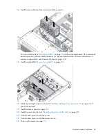
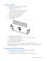
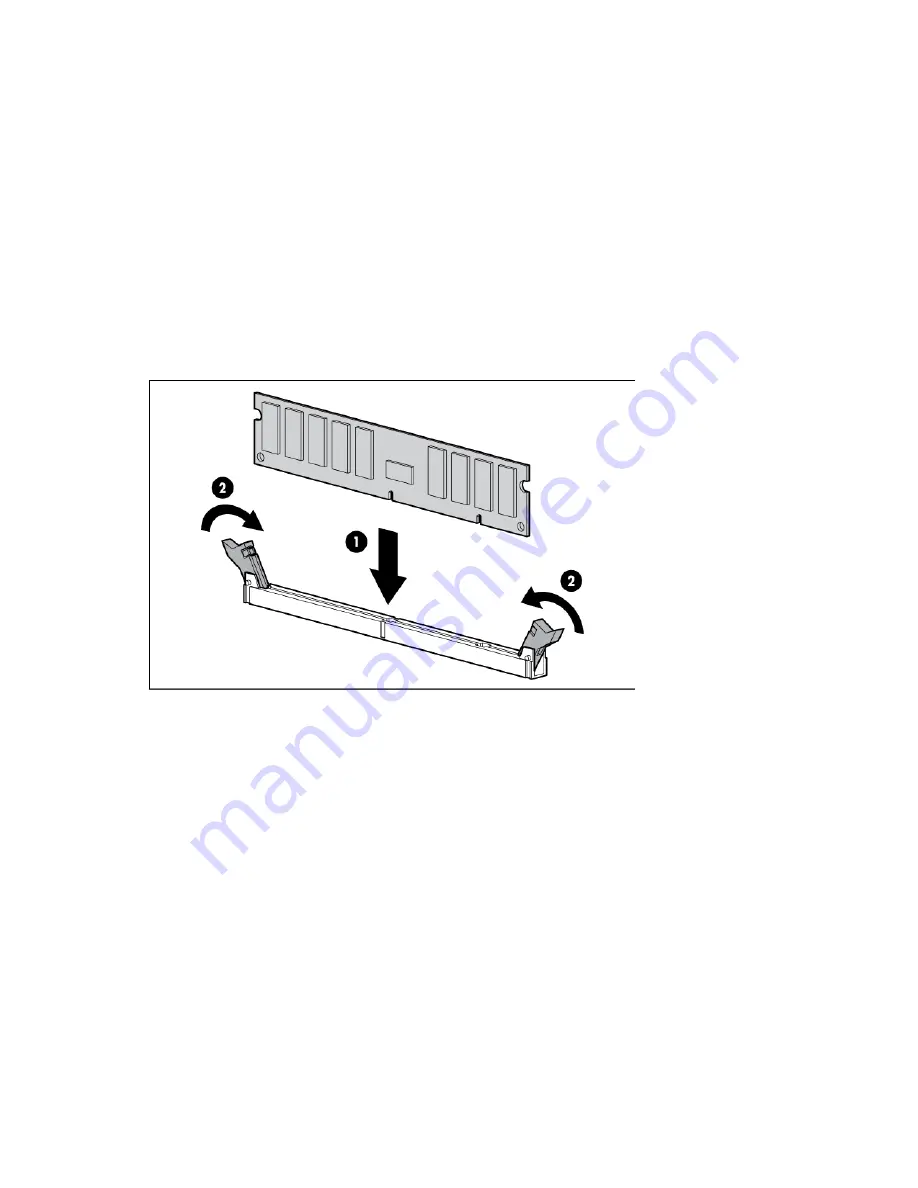
Open the DIMM slot latches. 

7.


Install the DIMM. 


8.


Install the access panel (on page 

25

). 

9.


Install the server into the rack ("

Installing the server into the rack

" on page 

38

). 

10.


Connect each power cord to the server. 

11.


Connect each power cord to the power source. 

12.


Power up the server (on page 

23

). 

Use RBSU ("

HP ROM-Based Setup Utility

" on page 

104

) to configure the memory mode. 

For more information about LEDs and troubleshooting failed DIMMs, see "Systems Insight Display LED 

combinations (on page 

12

)." 


Hot-plug hard drive options 

When adding hard drives to the server, observe the following general guidelines:   


The system automatically sets all device numbers. 


If only one hard drive is used, install it in the bay with the lowest device number. 

Summary of Contents for ProLiant DL380p Gen8

Page 1: ...r the person who installs administers and troubleshoots servers and storage systems HP assumes you are qualified in the servicing of computer equipment and trained in recognizing hazards in products with hazardous energy levels Part Number 661848 004 March 2013 Edition 4 ...

Page 2: ...oducts and services are set forth in the express warranty statements accompanying such products and services Nothing herein should be construed as constituting an additional warranty HP shall not be liable for technical or editorial errors or omissions contained herein Microsoft Windows and Windows Server are U S registered trademarks of Microsoft Corporation ...

Page 3: ...Power down the server 23 Extend the server from the rack 23 Remove the access panel 24 Install the access panel 25 Access the product rear panel 25 Opening the cable management arm 25 Remove the hot plug fan cage 26 Remove the hot plug fan 27 Remove the full length expansion board 28 Remove the PCI riser cage 29 Install the PCI riser cage 30 Secure the full length expansion board retainer 31 Remov...

Page 4: ...tor pack 59 Optical drive option 63 Redundant hot plug power supply option 65 48V DC power supply option 66 FlexibleLOM option 70 Expansion board options 72 Removing the expansion slot blanks 72 Installing a half length expansion board 73 Installing a full length expansion board 74 Secondary PCI riser cage option 75 Hard drive cage option 77 2U rack bezel option 86 HP Trusted Platform Module optio...

Page 5: ...ry replacement 112 Regulatory information 113 Safety and regulatory compliance 113 Turkey RoHS material content declaration 113 Ukraine RoHS material content declaration 113 Warranty information 113 Electrostatic discharge 114 Preventing electrostatic discharge 114 Grounding methods to prevent electrostatic discharge 114 Specifications 115 Environmental specifications 115 Mechanical specifications...

Page 6: ...Contents 6 Index 131 ...

Page 7: ...rive Item Description 1 Video connector 2 SATA optical drive bay 3 Drive bays 4 Systems Insight Display 5 USB connectors 2 SFF model with optional hard drive cage 16 drive Item Description 1 Video connector 2 Drive bays box 1 3 Drive bays box 2 4 Systems Insight Display 5 USB connectors 2 ...

Page 8: ...el 25 drive Item Description 1 Video connector 2 Quick release levers 2 3 Drive bays 4 USB connector LFF model 8 drive Item Description 1 Video connector 2 SATA optical drive bay 3 Drive bays 4 Systems Insight Display 5 USB connectors 2 ...

Page 9: ...uick release levers 2 3 Drive bays 4 USB connector Front panel LEDs and buttons Item Description Status 1 Power On Standby button and system power LED Solid green System on Flashing green 1 Hz cycle per sec Performing power on sequence Solid amber System in standby Off No power present ...

Page 10: ...cle per sec Remote management or firmware upgrade in progress Off Deactivated Facility power is not present power cord is not attached no power supplies are installed power supply failure has occurred or the power button cable is disconnected To identify components in a degraded or critical state see the Systems Insight Display LEDs check iLO BIOS logs and reference the server troubleshooting guid...

Page 11: ...o link to network If the power is off view the rear panel RJ 45 LEDs for status Rear panel LEDs and buttons on page 14 Flashing green Network link and activity Solid green Network link 3 AMP status Off AMP modes disabled Solid green AMP mode enabled Solid amber Failover Flashing amber Invalid configuration 4 Over temp Off Normal Solid amber High system temperature detected All other LEDs Off Norma...

Page 12: ...he Health Driver has detected a cautionary temperature level Over temp amber Red Amber The server has detected a hardware critical temperature level PCI riser amber Red Green The PCI riser cage is not seated properly Fan amber Amber Green One fan has failed or has been removed Fan amber Red Green Two or more fans have failed or been removed Power supply amber Red Amber One or more of the following...

Page 13: ...DIMM by replacing each DIMM in a bank with a known working DIMM Rear panel components Item Description 1 PCIe slots 1 3 top to bottom 2 PCIe slots 4 6 top to bottom 3 Power supply 1 PS1 4 PS1 power connector 5 PS2 power connector 6 Power supply 2 PS2 7 USB connectors 4 8 Video connector 9 iLO connector 10 Serial connector 11 FlexibleLOM ports Shown 4x1Gb Optional 2x10Gb port 1 on right side ...

Page 14: ...k activity Solid green Link to network Flashing green Network activity Non hot plug PCI riser board slot definitions Primary riser cage connector connected to processor 1 or the southbridge PCIe 3 slot riser cage PCIe 2 slot x16 riser cage 1 FL FH PCIe2 or PCIe3 x16 16 8 4 2 1 2 HL FH PCIe2 or PCIe3 x8 8 4 2 1 3 HL FH PCIe2 x8 4 2 1 Secondary riser cage connector connected to processor 2 Processor...

Page 15: ...stalled in the primary riser connector Secondary denotes the riser cage is installed in the secondary riser connector Installing the riser cages listed in the table above in either the primary or secondary riser connectors determines the form factor of the PCI cards supported by those riser cages FL FH denotes full length full height HL FH denotes half length full height LP denotes low profile The...

Page 16: ...nnector 17 Power supply backplane connector 18 SATA optical drive connector 19 NMI jumper 20 System battery 21 SD card slot 22 Secondary processor 2 PCI riser connector 23 System maintenance switch 24 Processor 2 socket 25 TPM connector 26 Primary processor 1 PCI riser connector 27 FlexibleLOM 28 SAS connector 1 29 SAS connector 2 30 Cache module connector 31 Processor 1 socket 32 RDX power connec...

Page 17: ... An NMI crash dump enables administrators to create crash dump files when a system is hung and not responding to traditional debug mechanisms Crash dump log analysis is an essential part of diagnosing reliability problems such as hangs in operating systems device drivers and applications Many crashes freeze a system and the only available action for administrators is to cycle the system power Rese...

Page 18: ...ts are numbered sequentially 1 through 12 for each processor The supported AMP modes use the letter assignments for population guidelines SAS and SATA device numbers SFF 8 device bay numbering Optional SFF 16 device bay numbering SFF 25 device bay numbering ...

Page 19: ...mbering Drive LED definitions Item LED Status Definition 1 Locate Solid blue The drive is being identified by a host application Flashing blue The drive carrier firmware is being updated or requires an update 2 Activity ring Rotating green Drive activity Off No drive activity ...

Page 20: ...tripe size migration capacity expansion or logical drive extension or is erasing Flashing amber green The drive is a member of one or more logical drives and predicts the drive will fail Flashing amber The drive is not configured and predicts the drive will fail Solid amber The drive has failed Off The drive is not configured by a RAID controller PCI riser cage LED CAUTION To prevent damage to the...

Page 21: ...the capacitor pack is charged Off On On The cache module is idle the capacitor pack is charged and the cache contains data that has not yet been written to the drives Off Flashing 1 Hz Off A backup is in progress Off On Off The current backup is complete with no errors Flashing 1 Hz Flashing 1 Hz Off The current backup failed and data has been lost Flashing 1 Hz Flashing 1 Hz On A power error occu...

Page 22: ... for redundancy A fan failure or missing fan causes a loss of redundancy A second fan failure or missing fan causes an orderly shutdown of the server The server supports variable fan speeds The fans operate at minimum speed until a temperature change requires a fan speed increase to cool the server The server shuts down during the following temperature related scenarios At POST and in the OS HP iL...

Page 23: ...on for more than 4 seconds to force the server to enter standby mode This method forces the server to enter standby mode without properly exiting applications and the OS If an application stops responding you can use this method to force a shutdown Use a virtual power button selection through HP iLO This method initiates a controlled remote shutdown of applications and the OS before the server ent...

Page 24: ...tches and sliding the server into the rack The sliding rails could pinch your fingers Remove the access panel WARNING To reduce the risk of personal injury from hot surfaces allow the drives and the internal system components to cool before touching them CAUTION For proper cooling do not operate the server without the access panel baffles expansion slot covers or blanks installed If the server sup...

Page 25: ...latch handle and then remove the access panel Install the access panel 1 Place the access panel on top of the server with the hood latch open Allow the panel to extend past the rear of the server approximately 1 25 cm 0 5 in 2 Push down on the hood latch The access panel slides to a closed position 3 Use a T 15 Torx screwdriver to tighten the security screw on the hood latch Access the product rea...

Page 26: ...an cage To remove the component 1 Power down the server on page 23 2 Remove all power a Disconnect each power cord from the power source b Disconnect each power cord from the server 3 Extend Extend the server from the rack on page 23 or remove the server from the rack 4 Remove the access panel on page 24 5 Remove the air baffle on page 32 ...

Page 27: ... that can lead to thermal damage IMPORTANT For optimum cooling install fans in all primary fan locations For more information refer to the fan locations table Hot plug fans on page 21 To replace the component reverse the removal procedure Remove the hot plug fan To remove the component 1 Extend or remove the server from the rack Extend the server from the rack on page 23 2 Remove the access panel ...

Page 28: ...ury electric shock or damage to the equipment remove the power cord to remove power from the server The front panel Power On Standby button does not completely shut off system power Portions of the power supply and some internal circuitry remain active until AC power is removed To remove the component 1 Power down the server on page 23 2 Remove all power a Disconnect each power cord from the power...

Page 29: ... PCI riser cage CAUTION To prevent damage to the server or expansion boards power down the server and remove all AC power cords before removing or installing the PCI riser cage 1 Power down the server on page 23 2 Remove all power a Disconnect each power cord from the power source b Disconnect each power cord from the server 3 Extend the server from the rack on page 23 4 Remove the access panel on...

Page 30: ...ove the power cord to remove power from the server The front panel Power On Standby button does not completely shut off system power Portions of the power supply and some internal circuitry remain active until AC power is removed 1 Power down the server on page 23 2 Remove all power a Disconnect each power cord from the power source b Disconnect each power cord from the server 3 Extend the server ...

Page 31: ...ce 10 Power up the server on page 23 Secure the full length expansion board retainer 1 Power down the server on page 23 2 Remove all power a Disconnect each power cord from the power source b Disconnect each power cord from the server 3 Extend the server from the rack on page 23 4 Remove the access panel on page 24 5 Install a full length expansion board Installing a full length expansion board on...

Page 32: ...the server supports hot plug components minimize the amount of time the access panel is open To remove the component 1 Power down the server on page 23 2 Remove all power a Disconnect each power cord from the power source b Disconnect each power cord from the server 3 Extend or remove the server from the rack Extend the server from the rack on page 23 4 Remove the access panel on page 24 CAUTION D...

Page 33: ...Operations 33 5 Release the full length expansion board retainer and then remove the PCI riser cage 6 Remove the air baffle To replace the component reverse the removal procedure ...

Page 34: ...re Hardware support o 6 Hour Call to Repair o 4 Hour 24x7 Same Day o 4 Hour Same Business Day Software support o Microsoft o Linux o HP ProLiant Essentials HP SIM and RDP o VMware Integrated hardware and software support o Critical Service o Proactive 24 o Support Plus o Support Plus 24 Startup and implementation services for both hardware and software For more information on HP Care Pack Services...

Page 35: ...sults in improper cooling that can lead to thermal damage The 9000 and 10000 Series Racks provide proper server cooling from flow through perforations in the front and rear doors that provide 64 percent open area for ventilation CAUTION When using a Compaq branded 7000 series rack install the high airflow rack door insert PN 327281 B21 for 42U rack PN 157847 B21 for 22U rack to provide proper fron...

Page 36: ...o safely provide power to all devices Observe the following guidelines Balance the server power load between available AC supply branch circuits Do not allow the overall system AC current load to exceed 80 of the branch circuit AC current rating Do not use common power outlet strips for this equipment Provide a separate electrical circuit for the server Electrical grounding requirements The server...

Page 37: ...hing electrode conductor or to a bonding jumper from an earthing terminal bar or bus to which the DC supply system earthing electrode conductor is connected This equipment should be located in the same immediate area such as adjacent cabinets as any other equipment that has a connection between the earthed conductor of the same DC supply circuit and the earthing conductor and also the point of ear...

Page 38: ...materials and documentation necessary for installing the server All the rack mounting hardware necessary for installing the server into the rack is included with the rack or the server The contents of the server shipping carton include Server Power cord Hardware documentation Documentation CD and software products Rack mounting hardware In addition to the supplied items you might need Operating sy...

Page 39: ...rs 3 Connect the power cord to the rear of the server 4 Install the power cord anchors 5 Secure the cables to the cable management arm IMPORTANT When using cable management arm components be sure to leave enough slack in each of the cables to prevent damage to the cables when the server is extended from the rack 6 Connect the power cord to the AC power source ...

Page 40: ...oning can configure the server and install an operating system eliminating the need for SmartStart CDs and Smart Update Firmware DVDs To install an operating system on the server with Intelligent Provisioning local or remote a Connect the Ethernet cable between the network connector on the server and a network jack b Press the Power On Standby button c During server POST press the F10 key d Comple...

Page 41: ...r has been added or is embedded in the system the controller defaults to a RAID configuration based on the size and number of hard drives installed For more information on modifying the controller default settings see the documentation on the Documentation CD For more information on automatic configuration see the HP ROM Based Setup Utility User Guide on the Documentation CD or the iLO Management ...

Page 42: ...discharge Processor and fan option The server supports single and dual processor operation CAUTION To avoid damage to the processor and system board only authorized personnel should attempt to replace or install the processor in this server CAUTION To prevent possible server malfunction and damage to the equipment multiprocessor configurations must contain processors with the same part number IMPO...

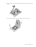
Page 43: ...e the full length expansion board retainer and then remove the PCI riser cage 6 Remove the air baffle on page 32 7 Open the heatsink retaining bracket and then remove the blank CAUTION The pins on the processor socket are very fragile Any damage to them may require replacing the system board ...

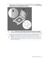
Page 44: ...installation 44 8 Open each of the processor locking levers in the order indicated and then open the processor retaining bracket 9 Remove the clear processor socket cover Retain the processor socket cover for future use ...

Page 45: ... VERY FRAGILE AND EASILY DAMAGED To avoid damage to the system board do not touch the processor or the processor socket contacts 11 Close the processor retaining bracket When the processor is installed properly inside the processor retaining bracket the processor retaining bracket clears the flange on the front of the socket CAUTION Do not press down on the processor Pressing down on the processor...

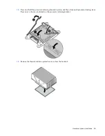
Page 46: ...2 Press and hold the processor retaining bracket in place and then close each processor locking lever Press only in the area indicated on the processor retaining bracket 13 Remove the thermal interface protective cover from the heatsink ...

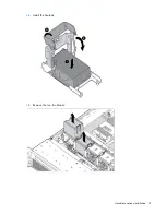
Page 47: ...Hardware options installation 47 14 Install the heatsink 15 Remove the two fan blanks ...

Page 48: ...on memory configurations see Memory Options on page 49 17 Install the air baffle Remove the air baffle on page 32 18 Install any full length expansion boards Installing a full length expansion board on page 74 if previously removed 19 Install the access panel on page 25 20 Install the server into the rack Installing the server into the rack on page 38 21 Connect each power cord to the server 22 Co...

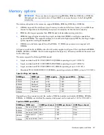
Page 49: ...r HDIMM the information applies to that type only All memory installed in the server must be the same type The server supports the following DIMM speeds Single and dual rank PC3 10600 DDR 1333 RDIMMs operating at up to 1333 MT s Single and dual rank PC3 12800 DDR 1600 RDIMMs operating at up to 1600 MT s Single and dual rank PC3 10600 DDR 1333 UDIMMs operating at up to 1333 MT s Quad rank PC3L 1060...

Page 50: ...emory 1 35V DDR3 1333 Registered memory is engineered to achieve the same performance level as 1 5V memory For example while the industry supports DDR3 1333 RDIMM at 1 5V this Gen8 server supports DDR3 1333 RDIMM up to 3 DIMMs per channel at 1066 MT s running at 1 35V This equates to up to 20 less power at the DIMM level with no performance penalty In addition the industry supports UDIMM at 2 DIMM...

Page 51: ...ty with the existing memory technology For example if current DRAM technology supports 8 GB single rank DIMMs a dual rank DIMM would be 16 GB and a quad rank DIMM would be 32 GB LRDIMMs are labeled as quad rank DIMMs however they function more like dual rank DIMMs There are four ranks of DRAM on the DIMM but the LRDIMM buffer creates an abstraction that allows the DIMM to appear as a dual rank DIM...

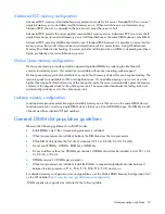
Page 52: ...of receiving an uncorrectable memory error which would result in system downtime to be removed from operation Advanced Memory Protection options are configured in RBSU If the requested AMP mode is not supported by the installed DIMM configuration the server boots in Advanced ECC mode For more information see HP ROM Based Setup Utility on page 104 The server also can operate in independent channel ...

Page 53: ...use If correctable memory errors occur at a rate higher than a specific threshold on any of the non spare ranks the server automatically copies the memory contents of the degraded rank to the online spare rank The server then deactivates the failing rank and automatically switches over to the online spare rank Lockstep memory configuration Lockstep mode provides protection against multi bit memory...

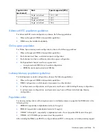
Page 54: ... o LRDIMMs are treated as dual rank DIMMs Lockstep Memory population guidelines For Lockstep memory mode configurations observe the following guidelines Observe the general DIMM slot population guidelines DIMM configuration on all channels of a processor must be identical In multi processor configurations each processor must have a valid Lockstep Memory configuration In multi processor configurati...

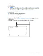
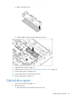
Page 55: ... page 25 9 Install the server into the rack Installing the server into the rack on page 38 10 Connect each power cord to the server 11 Connect each power cord to the power source 12 Power up the server on page 23 Use RBSU HP ROM Based Setup Utility on page 104 to configure the memory mode For more information about LEDs and troubleshooting failed DIMMs see Systems Insight Display LED combinations ...

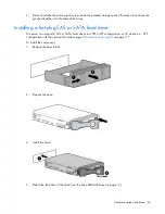
Page 56: ...g a hot plug SAS or SATA hard drive The server can support 8 SAS or SATA hard drives in a SFF or LFF configuration or 16 drives in a SFF configuration with the optional hard drive cage Hard drive cage option on page 77 To install the component 1 Remove the drive blank 2 Prepare the drive 3 Install the drive 4 Determine the status of the drive from the drive LED definitions on page 19 ...

Page 57: ...controller For a list of supported options see the QuickSpecs on the HP website http www hp com support The server supports FBWC FBWC consists of a cache module and a capacitor pack The DDR cache module buffers and stores data being written by the controller When the system is powered on the capacitor pack charges fully in about 5 minutes In the event of a system power failure a fully charged capa...

Page 58: ...er outage occurs When power is restored to the system an initialization process writes the preserved data to the hard drives Installing the flash backed write cache module CAUTION The cache module connector does not use the industry standard DDR3 mini DIMM pinout Do not use the controller with cache modules designed for other controller models because the controller can malfunction and you can los...

Page 59: ...ord to the server 12 Connect each power cord to the power source 13 Power up the server on page 23 Installing the flash backed write cache capacitor pack CAUTION The cache module connector does not use the industry standard DDR3 mini DIMM pinout Do not use the controller with cache modules designed for other controller models because the controller can malfunction and you can lose data Also do not...

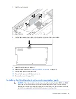
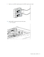
Page 60: ...not erroneously mark the drives as failed when the server is powered up 3 Power down the server on page 23 4 Remove all power a Disconnect each power cord from the power source b Disconnect each power cord from the server 5 Extend the server from the rack on page 23 6 Remove the access panel on page 24 7 Install the FBWC module Installing the flash backed write cache module on page 58 if it is not...

Page 61: ...Hardware options installation 61 9 Install one or two FBWC capacitor packs into the FBWC capacitor pack holder 10 Install the FBWC capacitor pack holder into the server o 8 or 16 drive SFF ...

Page 62: ...Hardware options installation 62 o 8 drive LFF o 12 drive LFF or 25 drive SFF or secondary location for 8 or 16 drive SFF or 8 drive LFF o Secondary location for 12 drive LFF or 25 drive SFF ...

Page 63: ...l on page 25 12 Install the server into the rack Installing the server into the rack on page 38 13 Connect each power cord to the server 14 Connect each power cord to the power source 15 Power up the server on page 23 Optical drive option 1 Power down the server on page 23 2 Remove all power a Disconnect each power cord from the power source ...

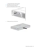
Page 64: ...ion 64 b Disconnect each power cord from the server 3 Extend the server from the rack on page 23 4 Remove the access panel on page 24 5 Remove the existing media drive option or blank 6 Slide the optical drive into the drive bay ...

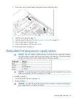
Page 65: ... must have the same output power capacity Verify that all power supplies have the same part number and label color The system becomes unstable and may shut down when it detects mismatched power supplies Label color Output Blue 460W Orange 750W White 750W 48V DC Green 1 200W CAUTION To prevent improper cooling and thermal damage do not operate the server unless all bays are populated with either a ...

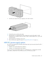
Page 66: ... reseller 6 Connect the power cord to the AC power source 7 Be sure that the power supply LED is green Rear panel LEDs and buttons on page 14 48V DC power supply option One of the following optional HP input cables with pre fastened ring tongues may be purchased from HP or an authorized reseller A5S97A 1 3 m 4 27 ft 48V DC Power Cable Kit A5S98A 2 5 m 8 20 ft 48V DC Power Cable Kit If you are not ...

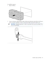
Page 67: ... not using an optional HP input cable with the ground cable disconnected from the 48V power source crimp the ring tongues to the power and ground cables coming from the 48V source IMPORTANT The power supply uses two power ring tongues and one ground ring tongue They are not interchangeable ...

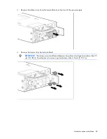
Page 68: ...m the terminal block on the front of the power supply 4 Remove the screws from the terminal block IMPORTANT The minimum nominal thread diameter of a pillar or stud type terminal must be 3 5 mm 0 138 in the diameter of a screw type terminal must be 4 0 mm 0 157 in ...

Page 69: ...asher and tighten to 1 47 N m 13 lb in of torque The ground wire must be connected before the positive or negative lead wires 6 Attach the power ring tongues to the terminal block following the polarity label below the terminal block and then tighten the screws to 1 47 N m 13 lb in of torque ...

Page 70: ...ent arm is available to help with routing To obtain a cable management arm contact an HP authorized reseller 10 Make sure the 48V DC power source is off or the PDU breaker is in the off position and then connect the power cord to the 48V DC power source or PDU 11 Turn on the 48V power source or switch the PDU breaker to the on position to supply 48V to the power supply 12 Be sure that the green po...

Page 71: ... off system power Portions of the power supply and some internal circuitry remain active until AC power is removed 1 Power down the server on page 23 2 Remove all power a Disconnect each power cord from the power source b Disconnect each power cord from the server 3 Remove any attached network cables 4 Extend the server from the rack on page 23 5 Remove the access panel on page 24 6 Loosen the thu...

Page 72: ...optional riser boards Removing the expansion slot blanks WARNING To reduce the risk of personal injury electric shock or damage to the equipment remove the power cord to remove power from the server The front panel Power On Standby button does not completely shut off system power Portions of the power supply and some internal circuitry remain active until AC power is removed CAUTION For proper coo...

Page 73: ...ard 7 Remove the PCIe riser cage Remove the PCI riser cage on page 29 8 Remove the expansion slot blank To replace the component reverse the removal procedure Installing a half length expansion board 1 Power down the server on page 23 2 Remove all power a Disconnect each power cord from the power source b Disconnect each power cord from the server 3 Extend the server from the rack on page 23 4 Rem...

Page 74: ...1 Install the server into the rack Installing the server into the rack on page 38 12 Connect each power cord to the server 13 Connect each power cord to the power source 14 Power up the server on page 23 Installing a full length expansion board 1 Power down the server on page 23 2 Remove all power a Disconnect each power cord from the power source b Disconnect each power cord from the server 3 Ext...

Page 75: ...erver into the rack on page 38 13 Connect each power cord to the server 14 Connect each power cord to the power source 15 Power up the server on page 23 Secondary PCI riser cage option WARNING To reduce the risk of personal injury electric shock or damage to the equipment remove the power cord to remove power from the server The front panel Power On Standby button does not completely shut off syst...

Page 76: ...nnect each power cord from the power source b Disconnect each power cord from the server 3 Extend the server from the rack on page 23 4 Remove the access panel on page 24 5 Remove the PCI riser blank 6 Remove the blank from the optional secondary PCI riser cage ...

Page 77: ...r and fan option on page 42 10 Install the access panel on page 25 11 Install the server into the rack Installing the server into the rack on page 38 12 Connect each power cord to the server 13 Connect each power cord to the power source 14 Power up the server on page 23 Hard drive cage option A SAS expander card or an additional SAS controller option is required to support the hard drive cage opt...

Page 78: ...ve all power a Disconnect each power cord from the power source b Disconnect each power cord from the server 3 Extend the server from the rack on page 23 4 Remove the access panel on page 24 5 Release the full length expansion board retainer and then remove the PCI riser cage 6 Remove the air baffle ...

Page 79: ...Hardware options installation 79 7 Remove the fan cage 8 Disconnect and remove the optical drive cable if installed ...

Page 80: ...nstallation 80 9 Using a T 15 Torx screwdriver remove the two optical drive retaining screws and then remove the optical drive cage 10 Install the optional hard drive cage 11 Install the hard drives and hard drive blanks ...

Page 81: ...ion 81 12 To access the cables remove the fan bracket on the right side of the chassis 13 Connect the cables a Connect one end of the power cable to the SAS backplane and the other end to the power connector on the system board ...

Page 82: ... Remove the existing SAS cable from the cable guide and from the system board 14 Connect the end of each SAS signal cable to the SAS backplane and then route the SAS signal cables behind the cable guide Do not connect the other ends yet ...

Page 83: ...Hardware options installation 83 15 Install the fan bracket Be sure that the cables are properly routed in the channel along the fan bracket 16 Remove the blank from the PCI riser cage ...

Page 84: ...Hardware options installation 84 17 Install the SAS controller board into the PCI riser cage 18 Install the fan cage 19 Install the air baffle ...

Page 85: ... end of the SAS signal cables to the SAS controller board and to the system board Then install the PCI riser cage SAS cables can be connected to the PCI riser cage and the system board before or after the PCI riser cage is installed For ease of accessing connectors HP recommends connecting the cables before the PCI riser cage is installed ...

Page 86: ...ll the server into the rack 24 Connect each power cord to the server 25 Connect each power cord to the power source 26 Power up the server on page 23 2U rack bezel option The 2U rack bezel helps prevent any unauthorized physical access to the server in the rack configuration To access the hard drive cage you must unlock and open the 2U rack bezel To unlock the 2U rack bezel use the key provided wi...

Page 87: ... Windows BitLocker Drive Encryption feature For more information on BitLocker see the Microsoft website http www microsoft com CAUTION Always observe the guidelines in this document Failure to follow these guidelines can cause hardware damage or halt data access When installing or replacing a TPM observe the following guidelines Do not remove an installed TPM Once installed the TPM becomes a perma...

Page 88: ...ive until AC power is removed WARNING To reduce the risk of personal injury from hot surfaces allow the drives and the internal system components to cool before touching them 1 Power down the server on page 23 2 Remove all power a Disconnect each power cord from the power source b Disconnect each power cord from the server 3 Remove the server from the rack if necessary 4 Place the server on a flat...

Page 89: ...ecovery key password The recovery key password is required to enter Recovery Mode after BitLocker detects a possible compromise of system integrity To help ensure maximum security observe the following guidelines when retaining the recovery key password Always store the recovery key password in multiple locations Always store copies of the recovery key password away from the server Do not save the...

Page 90: ...cked if you fail to follow the proper procedures for updating the system or option firmware replacing the system board replacing a hard drive or modifying OS application TPM settings For more information on firmware updates and hardware procedures see the HP Trusted Platform Module Best Practices White Paper on the HP website http www hp com support For more information on adjusting TPM usage in B...

Page 91: ...Cabling 91 Cabling SAS hard drive cabling SFF hard drive cabling SFF cabling with optional drive cage ...

Page 92: ...Cabling 92 LFF hard drive cabling Optical drive cabling ...

Page 93: ...Cabling 93 FBWC cabling 8 or 16 drive SFF 8 drive LFF ...

Page 94: ...chipset SATA cable option the chipset SATA controller can be used with a single SATA hard drive that is installed in one hard drive bay of the SFF or LFF hard drive cage When using the chipset SATA configuration the following conditions apply o Only drive bay 5 is enabled The remaining drive bays are disabled o The optical bay is disabled because the chipset SATA controller port on the system boar...

Page 95: ...n the server on page 23 2 Remove all power a Disconnect each power cord from the power source b Disconnect each power cord from the server 3 Extend the server from the rack on page 23 4 Remove the access panel on page 24 WARNING Eliminate the risk of electric shock by removing all AC power from the system before installing or replacing any non hot plug hardware option Disconnect all power cords to...

Page 96: ... cable from the optical drive and the SATA connector on the system board The optical bay is disabled with the chipset SATA cable option 10 Connect the chipset SATA cable a Connect the chipset SATA cable connector to the chipset SATA controller port on the system board The chipset SATA connector on the SATA cable is narrower than the chipset SATA controller port header on the system board ...

Page 97: ...rack Installing the server into the rack on page 38 18 Remove any installed hard drives Removing a hot plug SAS or SATA hard drive on page 57 19 Install a SATA hard drive Installing a hot plug SAS or SATA hard drive on page 56 in hard drive bay 5 20 Install hard drive blanks in any empty hard drive bays 21 Connect each power cord to the server 22 Connect each power cord to the power source 23 Powe...

Page 98: ...Cabling 98 Connect the cable as indicated ...

Page 99: ...on page 104 Offline Array Configuration Utility on page 106 Online and Offline Option ROM Configuration for Arrays on page 107 Offline ROMPaq utility on page 107 Offline HP product QuickSpecs For more information about product features specifications options configurations and compatibility see the product QuickSpecs on the HP Product Bulletin website http www hp com go productbulletin HP iLO Mana...

Page 100: ...bsite http www hp com go ilo docs Active Health System HP Active Health System provides the following features Combined diagnostics tools scanners Always on continuous monitoring for increased stability and shorter downtimes Rich configuration history Health and service alerts Easy export and upload to Service and Support The HP Active Health System monitors and records changes in the server hardw...

Page 101: ...ers SmartStart CDs and the Smart Update Firmware DVD will no longer ship with these new servers Instead the deployment capability is embedded in the server as part of HP iLO Management Engine s Intelligent Provisioning Intelligent Provisioning is an essential single server deployment tool embedded in HP ProLiant Gen8 servers that simplifies HP ProLiant server setup providing a reliable and consist...

Page 102: ... a significant change occurs between data gathering intervals the survey function marks the previous information and overwrites the survey data files to reflect the latest changes in the configuration Survey functionality is installed with every Intelligent Provisioning assisted HP Insight Diagnostics installation or it can be installed through the SPP HP Service Pack for ProLiant on page 103 Eras...

Page 103: ...deployment tool SPP can be used in an online mode on a Windows or Linux hosted operating system or in an offline mode where the server is booted to the ISO so that the server can be updated automatically with no user interaction or updated in interactive mode For more information or to download SPP see the HP website http www hp com go spp HP Smart Update Manager HP SUM is included in many HP prod...

Page 104: ... key during power up when prompted To navigate the menu system use the arrow keys To make selections press the Enter key To access Help for a highlighted configuration option press the F1 key IMPORTANT RBSU automatically saves settings when you press the Enter key The utility does not prompt you for confirmation of settings before you exit the utility To change a selected setting you must select a...

Page 105: ... the F10 key Access the boot menu by pressing the F11 key Force a PXE Network boot by pressing the F12 key Configuring AMP modes Not all HP ProLiant servers support all AMP modes RBSU provides menu options only for the modes supported by the server Advanced memory protection within RBSU enables the following advanced memory modes Advanced ECC Mode Provides memory protection beyond Standard ECC All...

Page 106: ... menu 10 Press the Esc key to exit RBSU 11 Press the F10 key to confirm exiting RBSU The server automatically reboots Utilities and features Array Configuration Utility ACU is a utility with the following features Runs as a local application or remote service accessed through the HP System Management Homepage Supports online array capacity expansion logical drive extension assignment of online spa...

Page 107: ...urations The utility also provides support for the following functions Reconfiguring one or more logical drives Viewing the current logical drive configuration Deleting a logical drive configuration Setting the controller to be the boot controller Selecting the boot volume If you do not use the utility ORCA will default to the standard configuration For more information regarding the default confi...

Page 108: ...USB device drivers Before the OS loads HP provides support for USB devices through legacy USB support which is enabled by default in the system ROM Legacy USB support provides USB functionality in environments where USB support is not available normally Specifically HP provides legacy USB functionality for the following POST RBSU Diagnostics DOS Operating environments which do not provide native U...

Page 109: ...and click Go Software and firmware Software and firmware should be updated before using the server for the first time unless any installed software or components require an older version For system software and firmware updates download the SPP HP Service Pack for ProLiant on page 103 from the HP website http www hp com go spp Version control The VCRM and VCA are web enabled Insight Management Age...

Page 110: ...your behalf HP Proactive Care For customers running business critical environments where down time is not an option then HP Proactive Care helps to deliver high levels of application availability Key to these service options is the delivery of proactive service management offers to help you avoid the causes of down time If a problems arises than HP offers advanced technical response from critical ...

Page 111: ...rman http www hp com support ProLiant_TSG_v1_gr Japanese http www hp com support ProLiant_TSG_v1_jp Simplified Chinese http www hp com support ProLiant_TSG_v1_sc The HP ProLiant Gen8 Troubleshooting Guide Volume II Error Messages provides a list of error messages and information to assist with interpreting and resolving error messages on ProLiant servers and server blades To view the guide select ...

Page 112: ...semble crush puncture short external contacts or dispose of in fire or water Replace only with the spare designated for this product To remove the component 1 Power down the server on page 23 2 Remove all power a Disconnect each power cord from the power source b Disconnect each power cord from the server 3 Extend Extend the server from the rack on page 23 or remove the server from the rack 4 Remo...

Page 113: ...p www hp com support Safety Compliance EnterpriseProducts Turkey RoHS material content declaration Ukraine RoHS material content declaration Warranty information HP ProLiant and X86 Servers and Options http www hp com support ProLiantServers Warranties HP Enterprise Servers http www hp com support EnterpriseServers Warranties HP Storage Products http www hp com support Storage Warranties HP Networ...

Page 114: ...atic sensitive component or assembly Grounding methods to prevent electrostatic discharge Several methods are used for grounding Use one or more of the following methods when handling or installing electrostatic sensitive parts Use a wrist strap connected by a ground cord to a grounded workstation or computer chassis Wrist straps are flexible straps with a minimum of 1 megohm 10 percent resistance...

Page 115: ...l specifications Specification Value Height 8 73 cm 3 44 in Depth SFF 69 85 cm 27 54 in Depth LFF 74 93 cm 29 5 in Width 44 54 cm 17 54 in Weight maximum all LFF drives 27 66 kg 61 0 lb Weight minimum one SFF drive 18 59 kg 41 0 lb Power supply specifications Depending on installed options the server is configured with one of the following power supplies HP 460 W CS HE Power Supply 92 specificatio...

Page 116: ...200V to 240V AC input HP 460 W CS Platinum Power Supply 94 specifications Specification Value Input requirements Rated input voltage 100 to 120 VAC 200 to 240 VAC Rated input frequency 50 Hz to 60 Hz Rated input current 5 2 A at 100 VAC 2 5 A at 200 VAC Rated input power 517 W at 100V AC input 496 W at 200V AC input Btus per hour 1764 at 100V AC input 1694 at 200V AC input Power supply output Rate...

Page 117: ...nput current 8 5 A at 100 VAC 4 1 A at 200 VAC Maximum rated input power 843 W at 100V AC input 811 W at 200V AC input Btus per hour 2878 at 100V AC input 2769 at 200V AC input Power supply output Rated steady state power 750 W at 100V to 120V AC input 750 W at 200V to 240V AC input Maximum peak power 750 W at 100V to 120V AC input 750 W at 200V to 240V AC input HP 750 W 48V CS Power Supply specif...

Page 118: ...Hz Rated input current 9 1 A at 100 VAC 6 7 A at 200 VAC Maximum rated input power 897 W at 100V AC input 1321 W at 200V AC input Btus per hour 3408 at 120V AC input 4433 at 200V to 240V AC input Power supply output Rated steady state power 800 W at 100V AC input 900 W at 120V AC input 1200 W at 200V to 240V AC input Maximum peak power 800 W at 100V AC input 900 W at 120V AC input 1200 W at 200V t...

Page 119: ...cation number Applicable error messages Add on boards or hardware Third party hardware or software Operating system type and revision level HP contact information For United States and worldwide contact information see the Contact HP website http www hp com go assistance In the United States To contact HP by phone call 1 800 334 5144 For continuous quality improvement calls may be recorded or moni...

Page 120: ... selfrepair Réparation par le client CSR Les produits HP comportent de nombreuses pièces CSR Customer Self Repair réparation par le client afin de minimiser les délais de réparation et faciliter le remplacement des pièces défectueuses Si pendant la période de diagnostic HP ou ses partenaires ou mainteneurs agréés détermine que la réparation peut être effectuée à l aide d une pièce CSR HP vous l en...

Page 121: ...mento di costo solo in alcune zone In caso di necessità si può richiedere l assistenza telefonica di un addetto del centro di supporto tecnico HP Nel materiale fornito con una parte di ricambio CSR HP specifica se il cliente deve restituire dei componenti Qualora sia richiesta la resa ad HP del componente difettoso lo si deve spedire ad HP entro un determinato periodo di tempo generalmente cinque ...

Page 122: ...o socios de servicio de HP identifica que una reparación puede llevarse a cabo mediante el uso de un componente CSR HP le enviará dicho componente directamente para que realice su sustitución Los componentes CSR se clasifican en dos categorías Obligatorio componentes para los que la reparación por parte del usuario es obligatoria Si solicita a HP que realice la sustitución de estos componentes ten...

Page 123: ...en in de geïllustreerde onderdelencatalogus aangemerkt met Nee Afhankelijk van de leverbaarheid en de locatie worden CSR onderdelen verzonden voor levering op de eerstvolgende werkdag Levering op dezelfde dag of binnen vier uur kan tegen meerkosten worden aangeboden indien dit mogelijk is gezien de locatie Indien assistentie gewenst is belt u een HP Service Partner om via de telefoon technische on...

Page 124: ... horas pode ser feita mediante uma taxa adicional Se precisar de auxílio entre em contato com o Centro de suporte técnico da HP para que um técnico o ajude por telefone A HP especifica nos materiais fornecidos com a peça CSR de reposição se a peça com defeito deve ser devolvida à HP Nos casos em que isso for necessário é preciso enviar a peça com defeito à HP dentro do período determinado normalme...

Page 125: ...Support and other resources 125 ...

Page 126: ...Support and other resources 126 ...

Page 127: ...lity AMP Advanced Memory Protection ASR Automatic Server Recovery CSA Canadian Standards Association CSR Customer Self Repair DDDC Double Device Data Correction DDR double data rate FBWC flash backed write cache HDIMM HyperCloud DIMM IEC International Electrotechnical Commission iLO Integrated Lights Out ...

Page 128: ... nonmaskable interrupt NVRAM nonvolatile memory ORCA Option ROM Configuration for Arrays PCIe peripheral component interconnect express POST Power On Self Test PSP HP ProLiant Support Pack RBSU ROM Based Setup Utility RDIMM registered dual in line memory module RDP Rapid Deployment Pack SAS serial attached SCSI SATA serial ATA ...

Page 129: ...ow voltage SFF small form factor SIM Systems Insight Manager TMRA recommended ambient operating temperature TPM Trusted Platform Module UDIMM unregistered dual in line memory module UID unit identification UPS uninterruptible power system USB universal serial bus VCA Version Control Agent ...

Page 130: ...oviding documentation that meets your needs To help us improve the documentation send any errors suggestions or comments to Documentation Feedback mailto docsfeedback hp com Include the document title and part number version number or the URL when submitting your feedback ...

Page 131: ...DC power supply 36 66 default settings 53 diagnostic tools 99 102 107 108 diagnostics utility 102 DIMM identification 51 DIMM population guidelines 53 DIMM slot locations 18 DIMMs 18 51 DIMMs installation 55 DIMMs single and dual rank 51 drive LEDs 19 drivers 108 drives 19 E electrical grounding requirements 36 electrostatic discharge 114 enabling the Trusted Platform Module 89 environmental requi...

Page 132: ...hts Out iLO 99 Integrated Management Log IML 101 Intelligent Provisioning 99 101 J Japanese notice 113 L LEDs 12 19 LEDs front panel 19 LEDs hard drive 19 LEDs SAS hard drive 19 LEDs troubleshooting 20 111 lockstep memory 53 54 M mechanical specifications 115 memory 49 51 53 memory configurations 52 53 memory dump 17 memory subsystem architecture 50 memory configuration requirements 52 54 memory c...

Page 133: ...shipping carton contents 38 space and airflow requirements 35 specifications 115 116 117 118 specifications environmental 115 specifications mechanical 115 specifications power 115 116 117 118 specifications server 115 SPP 103 static electricity 114 support 119 supported operating systems 109 switches 17 system battery 112 system board components 15 system components 7 system maintenance switch 16...

Reviews: