7-2
Virtual LAN
VLAN Ports
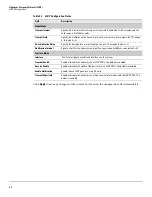
Table 7-1. VLAN Configuration Fields
Click
Apply
to save any changes for the currently selected VLAN. The changes take effect immediately.
VLAN Ports
Use the VLAN Ports page to view the Port VLAN ID that a port will assign to untagged frames that it
forwards, and to configure the port priority.
To display the VLAN Ports page, click
VLANs > VLAN Ports
in the navigation pane.
Figure 7-2. VLAN Ports Page
Table 7-2. VLAN Ports Fields
Field
Description
Create VLAN
Select this box to create a new VLAN.
Create VLAN ID
Specify the numeric VLAN Identifier from 2 to 4094 and click
Apply
to create the VLAN
.
Note:
VLAN ID 1 is pre-configured on the switch and is always named “Default.” The default
VLAN cannot be deleted.
Number of VLANs
The current number of VLANs. Up to 64 VLANs can be created.
VLAN Name
Delete VLAN
Set Name
After the VLAN ID has been created using the previously described fields, you can apply a name
to it or delete it.
• To delete a VLAN, select
Delete VLAN
and click
Apply
. The default VLAN cannot be deleted.
• To specify a VLAN name, select
Set Name
, type a name in the VLAN Name field, and click
Apply
. A VLAN name can have any case-sensitive combination of up to 32 alpha-numeric
characters and can contain ‘-’, ‘_’, and ‘.’ (a-z, A-Z, 0-9,-,_, and .).
Field
Description
Interface
Select the port on which to configure the VLAN settings.
PVID
The VLAN ID that this port will assign to untagged frames or priority-tagged frames received
on this port (range 1–4094, default = 1). The PVID is not user-configurable and always
corresponds to VLAN ID of the port’s untagged VLAN membership. You assign ports to VLANs
on the VLAN Participation / Tagging page.
The PVID value displays as
None
if all the VLANs are configured as tagged on this port or if this
port is configured as the destination port in a port mirroring configuration.
Port Priority
Specify the default 802.1p priority assigned to untagged packets arriving at the port. A value of
0 indicates the lowest priority, commonly used for routine traffic, and 7 indicates the highest
priority, often reserved for application such as voice and video. (0–7, default = 0)
Summary of Contents for PS1810 SERIES
Page 1: ...HP PS1810 Switches Management and Configuration Guide ...
Page 2: ......
Page 3: ...i HP PS1810 Switches Management and Configuration Guide June 2013 ...
Page 10: ...viii ...
Page 34: ...2 18 Status Clock ...
Page 54: ...4 12 Switching Spanning Tree ...
Page 60: ...5 6 Security Secure Connection ...
Page 70: ...7 6 Virtual LAN Advanced Configuration ...
Page 76: ...8 6 Link Layer Discovery Protocol LLDP Energy Efficient Ethernet ...
Page 82: ...9 6 Diagnostics Locator ...
Page 98: ...11 6 Servers Monitor Servers ...
Page 99: ......


