
EL-MF877-00 Page 10
Template Revision B
PSG instructions for this template are available at
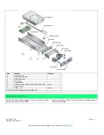
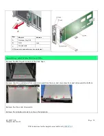
Item
Material
Hazards
A
Aluminium Alloy 380
B
PCB
Lead
C
Polycarbonate
All Screws, nuts and washers are zinc plated steel
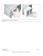
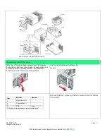
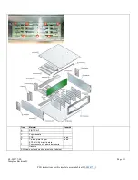
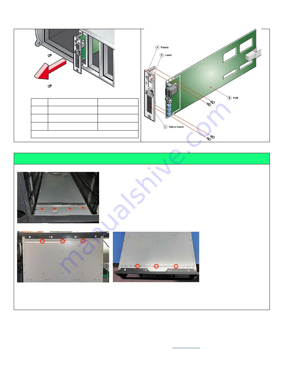
Disassembling Center Plane (aka Mid-Plane) PCBA:
Remove the EMI fingers from all of the drive bays.
Remove one drive wall screw from each drive wall from the top, and one screw from each drive wall the bottom.
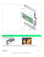
Remove the three mid drive-walls.
Remove the midplane screws to remove the midplane.


