background image

Page 4

792519-001 Edition 1

ENGLISH

Contents

Table of Contents

Contents .....................................................................................................................................4

1. Overview ...............................................................................................................................5

1.1 Environmental protection ....................................................................................................................................... 5
1.2 Weights and dimensions .......................................................................................................................................... 6
1.3 Rear panels .................................................................................................................................................................... 7

2. User Interface ......................................................................................................................8

2.1 Control panel ................................................................................................................................................................ 8
2.2 LCD window .................................................................................................................................................................. 9
2.3 Display functions ......................................................................................................................................................10
2.4 User settings ...............................................................................................................................................................10

3. Installation ......................................................................................................................... 12

3.1 Unpacking and contents check ...........................................................................................................................12
3.2 Battery module connection ..................................................................................................................................14
3.3 Tower installation ......................................................................................................................................................15
3.4 Rack installation ........................................................................................................................................................15
3.5 Communication ports .............................................................................................................................................19
3.6 UPS connection .........................................................................................................................................................20
3.7 Ground connection ..................................................................................................................................................21
3.8 ERM and UPS installation .......................................................................................................................................22

4. Operation ........................................................................................................................... 24

4.1 Start-up and normal operation ............................................................................................................................24
4.2 Starting the UPS on battery ..................................................................................................................................24
4.3 UPS shutdown ............................................................................................................................................................24
4.4 Operation on battery power .................................................................................................................................24
4.5 Return of AC input power ......................................................................................................................................25
4.6 UPS remote control functions ..............................................................................................................................25

5. Maintenance ..................................................................................................................... 26

5.1 Troubleshooting ........................................................................................................................................................26
5.2 Updating the UPS firmware ..................................................................................................................................26
5.3 Battery module replacement ...............................................................................................................................27
5.4 Spares ............................................................................................................................................................................28

6. Technical Specifications ................................................................................................ 29

6.1 HP R/T2200 G4 NA/JP UPS and HP R/T3000 G4 LV NA/JP UPS .................................................................29
6.2 HP R/T3000 G4 HV NA/JP UPS and HP R/T3000 G4 INTL UPS ...................................................................30

7. Support and other resources ...................................................................................... 31

Summary of Contents for R/T2200 G4 ERM

Page 1: ...the person who installs and maintains HP UPS products HP assumes you are qualified in the installation of electrical equipment and trained in recognizing hazards in products with hazardous energy levels Part Number 792519 001 November 17 2014 Edition 1 ...

Page 2: ... hazardous waste center IMPORTANT SAFETY INSTRUCTIONS SAVE THESE INSTRUCTIONS This manual contains important instructions that should be followed during installation and maintenance of the UPS and batteries The 2U UPS models that are covered in this manual are intended for installation in an environment within 0 to 40 C 32 to 104 F free of conductive contaminant For HP R T3000 HV NA JP and HP R T3...

Page 3: ...grounded supply circuit Product Safety The UPS connection instructions and operation described in the manual must be followed in the indicated order A protection circuit breaker must be installed upstream and be easily accessible The system can be disconnected from the AC power source by opening this circuit breaker Check that the indications on the rating plate correspond to your AC powered syste...

Page 4: ...munication ports 19 3 6 UPS connection 20 3 7 Ground connection 21 3 8 ERM and UPS installation 22 4 Operation 24 4 1 Start up and normal operation 24 4 2 Starting the UPS on battery 24 4 3 UPS shutdown 24 4 4 Operation on battery power 24 4 5 Return of AC input power 25 4 6 UPS remote control functions 25 5 Maintenance 26 5 1 Troubleshooting 26 5 2 Updating the UPS firmware 26 5 3 Battery module ...

Page 5: ...yethylene terephthalat PET 01 High density polyethylene HDPE 02 Polyvinyl chloride PVC 03 Low density polyethylene LDPE 04 Polypropylene PP 05 Polystyrene PS 06 Follow all local regulations for the disposal of packing materials End of life HP processes products at the end of their service lives in compliance with local regulations HP works with companies in charge of collecting and eliminating our...

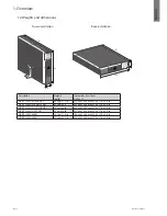
Page 6: ...442 x 86 mm 20 6 x 17 4 x 3 4 in HP R T3000 G4 LV NA JP UPS 39 9 kg 88 0 645 x 442 x 86 mm 25 4 x 17 4 x 3 4 in HP R T3000 G4 HV NA JP UPS 38 kg 83 8 lb 645 x 442 x 86 mm 25 4 x 17 4 x 3 4 in HP R T3000 G4 INTL UPS 38 kg 83 8 lb 645 x 442 x 86 mm 25 4 x 17 4 x 3 4 in HP R T2200 G4 ERM 32 2 kg 71 0 lb 508 x 442 x 86 mm 20 0 x 17 4 x 3 4 in HP R T3000 G4 ERM 45 2 kg 99 7 lb 648 x 442 x 86 mm 25 5 x ...

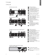
Page 7: ...lets for connection of equipment 8b Group 2 Two programmable outlets for connection of equipment 9 Primary Group outlets for connection of critical equipment 10 Attached 8 ft input power cord for AC power source 5 20P for 2200 L5 30P for 3000 11 LED indicating SWF site wiring fault alarm Although the LED remains on the rear panel this feature is disabled for low voltage models 12 Ground connection...

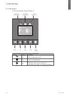
Page 8: ...m Indicator red Normal mode 100 17min 1ERM 100 2 7kW 3kVA Efficiency 98 Escape Up Down Enter On Off button The following table shows the indicator status and description Indicator Status Description Green On The UPS is operating normally Yellow On The UPS is on Battery mode Red On The UPS has an active alarm or fault See 5 1 Troubleshooting on page 26 for additional information ...

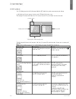
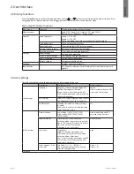
Page 9: ... UPS is off waiting for start up com mand from user Equipment is not powered until the button is pressed Normal mode The UPS is operating normally The UPS is powering and protecting the equipment In Automatic Voltage Regulation mode No audio alarm The UPS is operating normally but the utility voltage is outside normal mode thresholds The UPS is powering the equipment through an AVR device The equi...

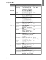
Page 10: ...splays the options that can be changed by the user Description Available settings Default settings Local settings Language English French German Spanish Italian Portuguese Russian Menus status notices and alarms UPS fault event log data and settings are in all supported languages English User selectable when the UPS is powered the first time LCD settings Allows LCD screen brightness and contrast t...

Page 11: ...Energy saving Disable Enable If enabled the UPS will shutdown after five minutes if no load is detected on the output Disable Sleep mode Disable Enable If enabled LCD and communication stays on 1h and 30 min after UPS turns off If disabled LCD and communication will turn off immediately after the UPS turns off Disable Remote command Disable Enable If enabled shutdown or restart commands from softw...

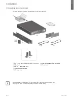
Page 12: ...n the packing materials to facilitate sorting 3 Installation 3 1 Unpacking and contents check HP R T2200 G4 NA JP UPS and HP R T3000 G4 LV NA JPN UPS 14 15 21 20 18 16 17 14 HP R T2200 G4 NA JP and HP R T3000 G4 LV NA JPN 15 Bezel parts 16 RS 232 communication cable 17 USB communication cable 18 Documentation 20 Mounting brackets rails and hardware 21 Tower stands ...

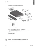
Page 13: ... for NA JP model Country specific cord for INTL model 32 Two connection cables for the protected equipment 33 RS 232 communication cable 34 USB communication cable 35 Two cable locking systems 36 Documentation 38 Mounting brackets rails and hardware 39 Tower stands Packing materials must be disposed of in compliance with all local regulations concerning waste Recycling symbols are printed on the p...

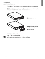
Page 14: ... small amount of arcing may occur when connecting the batteries This is normal and does not damage the UPS or present any safety concern A C B Installing the new battery module Perform the removal instructions in reverse order To ensure safety and high performance only use batteries supplied by HP Take care to firmly press together the two parts of the connector during remounting A Connect the bat...

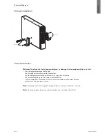
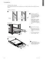
Page 15: ...rack rests on the leveling feet The stabilizing feet are attached to the rack if it is a single rack installation The racks are coupled together in multiple rack installations Only one component is extended at a time A rack may become unstable if more than one component is extended for any reason Note If preparing the rails for integrated shipping follow the same rack installation instructions Not...

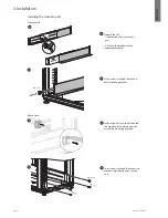
Page 16: ...wing nuts or hex nuts 2 Extend the brackets to the appropriate length B Insert screws through the rail and each mounting bracket M6 screws C Install cage nuts or clip nuts behind the mouting holes where you will attach the mounting brackets D Insert screws through the mounting brackets into the cage nuts or clip nuts A B C D 3 Installation ...

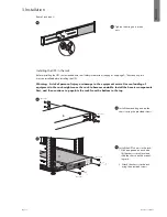
Page 17: ... equipment in the rack might cause the rack to become unstable Install the heavier components first and then continue to populate the rack from the bottom to the top M3 screws M3 screws M6 screws M6 screws E Tighten the wing nuts or hex nuts A Install the mounting ears on the chassis using the provided screws B Install the UPS chassis in the rack 1 With one person on each side lift the chassis to ...

Page 18: ...rear rail stabilizing bracket to screws in the rail see dia gram for position Repeat on the other rail 2 Wait until the unit is installed and the brackets are adjusted before tightening the nuts See the diagram at the left for inner and outer rail installation views B Reinstall the UPS chassis in the rack 1 With one person on each side lift the chassis to rail level and slide the chassis on the mo...

Page 19: ... software Installation of optional NMC Network Card It is not necessary to shut down the UPS before installing a communication card 1 Remove the mounting screws and remove the slot cover 4 2 Insert the communication card in the slot 3 Secure the card cover with the screws removed in Step 1 When a signal is activated the contact is closed between the common pin 2 and the pin for the corresponding s...

Page 20: ...ra tion on battery power see 2 4 User settings on page 10 The UPS charges the battery as soon as it is connected to the AC power source even if the button is not pressed After the UPS is connected to the AC power source eight hours of charging is required before the battery can supply the rated backup time 1 Connect the UPS input plug 10 to the AC power source 2 Connect the loads to the UPS It is ...

Page 21: ...ore the battery can supply the rated backup time 1 Connect the supplied cable 31 250V 16A to the socke 10 then to the AC power source 2 Connect the loads to the UPS using the cables 32 It is preferable to connect the priority loads to the four outlets marked 9 and the non priority loads to the four outlets marked 8 that can be programmed in pairs 1 and 2 For the R T3000 G4 HV NA JP HV and R T3000 ...

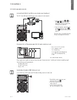
Page 22: ... on the rails M3 screws M3 screws M3 screws M6 screws M6 screws M6 screws M6 screws M6 screws M6 screws 4 4 3 3 2 2 1 1 3 8 ERM and UPS installation There are two ERM models They can be installed with UPSs in both rack and tower installations Up to four ERMs can be installed with each UPS HP R T3000 G4 ERM HP R T2200 G4 ERM ...

Page 23: ...ition 1 ENGLISH Tower configuration 1 x ERM 2 x ERM M3 screws Note The connected power cord between UPS and ERM must be provided by original manufacturer only 3 Installation ERM and UPS connection Rack configuration 1 x ERM 2 x ERM ...

Page 24: ...e 1011 To start the UPS on battery 1 Press the button on the UPS control panel until the UPS LCD window illuminates and displays UPS starting The UPS cycles through Standby mode to Battery mode The indicator illuminates The UPS supplies power to your equipment 2 Check the UPS LCD window display for active alarms or notices You should see the Battery mode notice and notices that indicate missing ut...

Page 25: ...of the button to shut down the UPS Access these functions by opening a contact connected between the appropriate pins of connector 5 on the rear panel of the UPS 5 Remote control connection and test 1 Check that the UPS is off and disconnected from the AC input source 2 Remove the connector 5 3 Connect a normally closed volt free contact 60 Vdc 30 Vac max 20 mA max 0 75 mm2 18 AWG cable cross sect...

Page 26: ...ontinues to operate but may shutdown if the load increases The alarm resets when the condition becomes inactive End of battery life The end of the battery life is reached Contact your service representative for battery replacement Event An UPS event occurs Example The RPO contact has been activated to shutdown the UPS and now prevents restart For this event set the contact back to its normal posit...

Page 27: ...me Important battery safety information Warning The unit contains sealed lead acid battery modules To prevent fire or chemical burns Do not attempt to recharge batteries after removal from the unit Do not disassemble crush or puncture the batteries Do not short the external contacts of the batteries Do not immerse the batteries in water Do not expose to temperatures higher than 60 C 140 F Battery ...

Page 28: ... pro tection cover in front of the battery E Pull the plastic tab to remove the battery block and replace the block 5 4 Spares Ordering Spares To order a spare visit the HP website http www hp com buy parts To replace parts under warranty contact an HP authorized service representative UPS spare parts list Item Spare Part Number SPS UPS R T2200 G4 NA JP 796757 001 SPS UPS R T3000 G4 LV NA JP 79675...

Page 29: ...Standard l Additional modules possible up to 4 ERMs 4 x 12V 9 Ah 6 x 12V 9 Ah HP R T2200 G4 ERM 8 x 12V 9 Ah 2 strings of x4 HP R T3000 G4 ERM 12 x 12V 9 Ah 2 strings of x6 Environment l Operating temperature range l Storage temperature range l Relative humidity l Noise level 0 to 40 C 15 to 50 C 20 to 90 without condensation 45 dBA 50 dBA 1 The high and low thresholds can be adjusted using UPS se...

Page 30: ...emperature range l Storage temperature range l Relative humidity l Noise level 0 to 40 C 15 to 50 C 20 to 90 without condensation 45 dBA 50 dBA 1 The high and low thresholds can be adjusted using UPS settings up to 150 294V 2 Up to 40 Hz in low sensitivity mode programmable using UPS settings 3 Adjustable to 200 208 220 230 240V but must be set to the identical AC power source value When the UPS i...

Page 31: ... serial number Product model name and number Product identification number Applicable error messages Add on boards or hardware Third party hardware or software Operating system type and revision level HP contact information For United States and worldwide contact information see the Contact HP website http www hp com go assistance In the United States To contact HP by phone call 1 800 334 5144 For...

Reviews: