background image


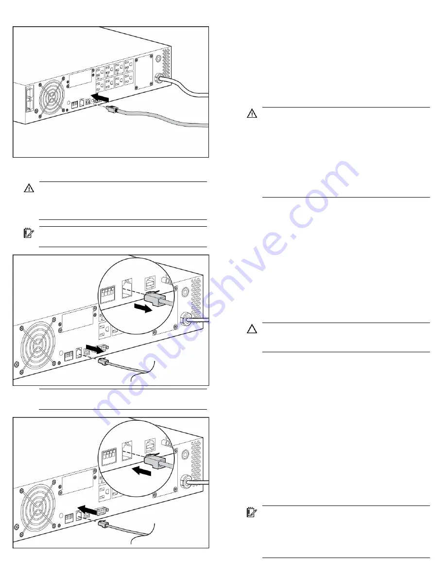
Connecting the REPO port 


WARNING:

  To meet the requirements stated in NEC 

(NFPA 70) Articles 645-10 and 645-11, a UPS installed in

a computer equipment room must be connected to a REPO 

circuit. 


IMPORTANT:

  The remote switch must be in the Off (open) 

position to enable power to the output receptacles. 


NOTE:

  Wire the connector block using stranded, 

nonshielded wire (AWG #22 - #18, or equivalent). 


Connecting the ground bonding cable 

The ground bonding screw is provided as an attachment point for 

conductors. Use a ground bonding cable if the rack contains any 

conductors for the purpose of functional grounding or bonding of 
ungrounded metal parts. 

The ground bonding cable is not included. 


Connecting the UPS to utility power 


WARNING:

  To prevent injury from electric shock or 

damage to the equipment: 


Plug the input line cord into a grounded (earthed) 
electrical outlet that is installed near the equipment and 

is easily accessible. 


Do not disable the grounding plug on the input line 

cord. The grounding plug is an important safety 
feature. 


Do not use extension cords. 


1.


Connect the input power cord from an intended load device to 
the IEC-320-C20 input power receptacle on the UPS rear panel 

(INTL model only). 

2.


Connect the UPS power cord to a grounded utility power 
outlet. When the UPS is plugged in, the batteries begin to 
charge. Power to the output receptacles designated for surge 

and battery backup is not available until the unit is powered 

up. 

For more information about receptacle control, see "Power 

management software" in the user guide. 


Connecting devices to the UPS 


CAUTION:

  Do not plug laser printers into the UPS output 

receptacles. The instantaneous current drawn by this type 
of printer can overload the UPS. 


Before connecting devices, verify that the UPS will not overload by 

checking that the ratings of the devices do not exceed the UPS 
capacity. If the equipment rating is listed in amps, multiply the 

number of amps by 120 (for Japan, by 100) to determine the VA. 

After verifying that the UPS will not overload: 


Connect the device power cords to the output receptacles on 
the rear panel of the UPS (NA/JPN/TWN model). 

-or- 


Connect devices to the output receptacles on the rear panel of 
the UPS using the jumper cords included with the UPS (INTL 

model). 


Charging the UPS batteries 

Allow the batteries to charge before putting the UPS into service. 


IMPORTANT:

  Charge the batteries for at least 24 hours 

before supplying backup power to devices. The batteries 

charge to: 


90% of their capacity within 4 hours 


100% of their capacity within 24 hours 


Summary of Contents for R/T2200

Page 1: ...cautions and hazards associated with AC power products WARNING To prevent personal injury from earth conductor leakage current Do not operate the UPS while disconnected from the utility power source Disconnect load devices before disconnecting the UPS from the utility power source WARNING To prevent personal injury prepare the area and observe all materials handling procedures when transporting th...

Page 2: ... safe operation of the equipment must not be compromised Circuit overloading Consideration should be given to the connection of the equipment to the supply circuit and the effect that overloading of the circuits might have on overcurrent protection and supply wiring Appropriate consideration of equipment nameplate ratings should be used when addressing this concern Reliable earthing Reliable earth...

Page 3: ...The full weight of the rack rests on the leveling feet The stabilizing feet are attached to the rack if it is a single rack installation The racks are coupled together in multiple rack installations Only one component is extended at a time A rack may become unstable if more than one component is extended for any reason NOTE Mounting hardware for square and round holed racks is included in the UPS ...

Page 4: ...attempt to recharge batteries after removal from the unit Do not disassemble crush or puncture the batteries Do not short the external contacts of the batteries Do not immerse the batteries in water Do not expose to temperatures higher than 40 C 104 F WARNING To prevent personal injury from hazardous energy Remove watches rings or other metal objects Use tools with insulated handles Do not place t...

Page 5: ...r interface cable supplied with the UPS to connect the communications port to the host computer CAUTION Using a USB to serial converter cable will damage the UPS Connect the UPS to a host computer using either the USB cable or the DB9 serial cable included with the UPS Install HP Power Manager software 4 1 or later on the host computer See the HP website http www hp com go rackandpower to download...

Page 6: ...S rear panel INTL model only 2 Connect the UPS power cord to a grounded utility power outlet When the UPS is plugged in the batteries begin to charge Power to the output receptacles designated for surge and battery backup is not available until the unit is powered up For more information about receptacle control see Power management software in the user guide Connecting devices to the UPS CAUTION ...

Page 7: ...Powering up the UPS Press and hold the Power On Standby button until the UPS beeps The Power LED illuminates solid green indicating that power is available at the UPS output receptacles ...

Reviews: