Overview 7
UPS can extend backup power for an increased amount of time. Distribute the load as evenly as possible
across the UPS configuration to most efficiently use the powerful three-phase UPS design.
The UPS modes of operation allow the UPS to transfer seamlessly between AC, Battery, and Bypass modes
to supply power to connected devices without interruption. For more information, see "Working with UPS
modes of operation (on page
76
)." The power unit can use a built-in, time-based algorithm to switch between
utility and generator battery charging power levels when transferring operating modes. Using a lower
charge level while the UPS runs on generator power maximizes the output available to connected devices.
The Management Module provides additional features to receive generator commands. To set UPS battery
charge power levels, see "Configuring the battery charge power levels (on page
75
)."
Advanced monitoring and management features
The Management Module card reports detailed information to the Management Module web interface
where the information is graphically displayed. Many commands and functions can be customized from the
interface. Customizable setup options in the UPS Service Menu can also be accessed using the Management
Module card. The Management Module is designed specifically for the DirectFlow UPS. It is not intended for
installation in other UPS devices.
To install and initially configure the Management Module in the DirectFlow UPS, see "Installing the
Management Module card (on page
57
)" and "Accessing the Management Module (on page
63
)." For
details about using the Management Module card and web interface, see the
HP DirectFlow UPS
Management Module User Guide
on the HP website (
http://www.hp.com/support/DFUPS_MM_UG_en
).
Location Discovery Services for the UPS configuration
HP provides built-in location awareness of rack components, a capability that works hand-in-hand with
technology in the new HP Intelligent Series racks. Together, the technologies provide the rack identification
number and precise U location of the components. This information is communicated through power
management software.
HP R12000DF
Summary of Contents for R12000 XR
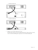
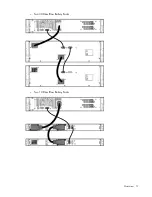
Page 17: ...Overview 17 o Two 3U DirectFlow Battery Packs o Two 1U DirectFlow Battery Packs ...
Page 98: ...Troubleshooting 98 ...
Page 99: ...Troubleshooting 99 ...
Page 100: ...Troubleshooting 100 ...
Page 101: ...Troubleshooting 101 ...
Page 102: ...Troubleshooting 102 ...
Page 103: ...Troubleshooting 103 ...
Page 104: ...Troubleshooting 104 ...
Page 105: ...Troubleshooting 105 ...
Page 106: ...Troubleshooting 106 ...
Page 107: ...Troubleshooting 107 ...
Page 108: ...Troubleshooting 108 ...
Page 109: ...Troubleshooting 109 ...
Page 110: ...Troubleshooting 110 ...
Page 111: ...Troubleshooting 111 ...


