background image


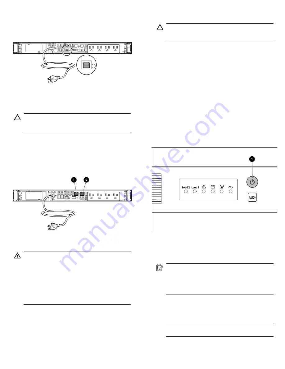
Connecting the USB communications port 


Connecting the Network Transient 

Protectors 


CAUTION:

  To avoid damaging the equipment, use the 

Network Transient Protector with a standard telephone line 
only, not with a digital PBX. 


To protect equipment against surges over a network data line: 

1.


Connect the network wall jack to the UPS Network Transient 
Protector IN jack. 

2.


Connect the equipment to the UPS Network Transient Protector 
OUT jack. 


Connecting the UPS to utility power 


WARNING:

  To prevent injury from electric shock or 

damage to the equipment: 


Plug the input line cord into a grounded (earthed) 

electrical outlet that is installed near the equipment and 
is easily accessible. 


Do not disable the grounding plug on the input line 

cord. The grounding plug is an important safety 
feature. 


Do not use extension cords. 


1.


Connect the input power cord to the IEC-320-C14 input power 
connector on the UPS rear panel (INTL model only). 

2.


Connect the UPS power cord to a grounded utility power outlet. 
When the UPS is plugged in, the batteries begin to charge. 

Power to the output receptacles designated for surge and battery 
backup is not available until the unit is powered up. 

For more information about receptacle control, see "Power protector 

software" in the user guide. 


Connecting devices to the UPS 


CAUTION:

  Do not plug laser printers into the UPS output 

receptacles. The instantaneous current drawn by this type 
of printer can overload the UPS. 


Before connecting devices, verify that the UPS will not overload by 
checking that the ratings of the devices do not exceed the UPS 
capacity. If the equipment rating is listed in amps, multiply the number 

of amps by the selected output voltage to determine the VA. 

After verifying that the UPS will not overload: 


Connect the device power cords to the output receptacles on the 
rear panel of the UPS (NA/JPN/TWN model). 

-or- 


Connect devices to the output receptacles on the rear panel of the 
UPS using the jumper cords included with the UPS (INTL model). 


Powering up the UPS 

Press and hold the Power On/Standby button (1) until the UPS beeps. 
The Power On, Load 1 and Load 2 LEDs illuminate, indicating that 
power is available at the UPS output receptacles. 


Charging the UPS batteries 

With the UPS in Standby mode, allow the batteries to charge before 
putting the UPS into service. 


IMPORTANT:

  Charge the batteries for at least 24 hours 

before supplying backup power to devices. The batteries 

charge to: 


90% of their capacity within 4 hours 


100% of their capacity within 24 hours 


Installing the optional UPS Network 

Module 


NOTE:

  It is not necessary to power down the UPS before 

installing the UPS Network Module. 


Summary of Contents for R1500 Generation 3

Page 1: ...HP UPS R1500 Generation 3 Installation Instructions Part Number 650952 001 ...

Page 2: ...rmining the class of the device refer to the user guide for complete regulatory compliance notices Kit contents Important Safety Information guide This document and or documentation CD HP Infrastructure Management Pack CD To download the latest software version see the HP website http www hp com go rackandpower Warranty information Rails with mounting hardware Mounting brackets with associated har...

Page 3: ...t item is on the bottom of the rack Install the heaviest item first and continue to populate the rack from the bottom to the top Installing the mounting rails WARNING To reduce the risk of personal injury or damage to the equipment be sure that The leveling feet are extended to the floor The full weight of the rack rests on the leveling feet The stabilizing feet are attached to the rack if it is a...

Page 4: ...ck using the supplied screws 3 optional Insert the rear stabilization brackets into the mounting rails and then attach the brackets to the UPS Connecting the batteries WARNING The unit contains sealed lead acid battery modules To prevent fire or chemical burns Do not attempt to recharge batteries after removal from the unit Do not disassemble crush or puncture the batteries Do not short the extern...

Page 5: ...ting more than one will result in unexpected UPS behavior If an option card is installed the serial and USB communications ports are automatically disabled Connect the UPS to a host computer using either the USB cable or the DB9 serial cable included with the UPS Install HP Power Protector on the host computer See the HP website http www hp com go rackandpower to download the latest version of HP ...

Page 6: ...e Power protector software in the user guide Connecting devices to the UPS CAUTION Do not plug laser printers into the UPS output receptacles The instantaneous current drawn by this type of printer can overload the UPS Before connecting devices verify that the UPS will not overload by checking that the ratings of the devices do not exceed the UPS capacity If the equipment rating is listed in amps ...

Page 7: ...the UPS is powered up you can be sure that the UPS Network Module is seated properly and communicating with the UPS by verifying that the UPS Data LED illuminates solid green and then flashes regularly after 2 minutes Connecting the UPS Network Module The UPS Network Module card is provided to manage the attached servers RJ 45 network patch panel cables are required to use this card The RJ 45 netw...

Page 8: ...warranties for HP products and services are set forth in the express warranty statements accompanying such products and services Nothing herein should be construed as constituting an additional warranty HP shall not be liable for technical or editorial errors or omissions contained herein Part Number 650952 001 January 2011 Edition 1 ...

Reviews: