background image

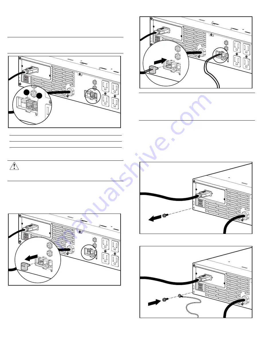
Connecting the Network Transient 
Protector 

The Network Transient Protector allows the UPS to protect a 
communications device from surges. 


IMPORTANT:

  To avoid damaging the equipment, use the Network 

Transient Protector with a standard telephone line only, not with a  
digital PBX. 


1

2


Item Description 

Network Transient Protector “IN” jack  

Network Transient Protector “OUT” jack 

Connecting the REPO Port 


WARNING:  If the UPS is to be installed in a computer equipment 
room, it must be connected to a REPO circuit. The REPO port is 
designed to meet the requirements stated in National Electrical 
Code (NFPA 70) Articles 645-10 and 645-11. 


The REPO port allows power to the UPS output receptacles to be 
switched off from a remote location. 
To activate the REPO port:  
1.  Install a suitable switch at the required remote location. 
2.  Remove the connector block from the REPO port. 


3.  Wire the connector block using stranded, non-shielded wire 

(AWG #22 - #18, or equivalent). 

4.  Replace the connector block in the REPO port. 


IMPORTANT:   

• 

The REPO port must meet the requirements of the NFPA Articles 
645-10 and 645-11 for a disconnecting means. 

• 

The remote switch must be in the Off (open) position to enable power 
to the output receptacles. 

Connecting the Ground Bonding Screw 

The ground bonding screw on the rear of the unit is provided as an 
attachment point for conductors. Use the ground bonding screw if 
the rack contains any conductors for the purpose of functional 
grounding or bonding of ungrounded metal parts. 
To connect the ground bonding screw: 
1.  Remove the ground bonding screw. 


2.  Attach the grounding cable and secure the ground  

bonding screw. 


Summary of Contents for R1500 XR SERIES

Page 1: ...onductor leakage current Do not operate a UPS that is disconnected from the utility power source Disconnect protected devices from the UPS before disconnecting the UPS from utility power Use the Test Alarm Reset button to test the batteries rather than unplugging the UPS Refer to the UPS user guide for more information on the operation of the UPS Regulatory Compliance Identification Numbers For re...

Page 2: ...te tool 2U 295523 023 UPS UPS chassis Front bezel Rear stabilization brackets 2 Remote Emergency Power Off REPO port and connector block Battery pack 1 Additional Hardware The following items are supplied for shipping a rack with a UPS installed M6 nuts 4 M6 flat washers 4 M6 split washers 4 Cables The R1500 XR NA model ships with a non detachable input power cord with a NEMA 5 15 plug and a 3 66 ...

Page 3: ...near the rack where it will be assembled Follow the unpacking instructions on the carton Mounting the Rails The UPS must be mounted on the fixed rails supplied with the UPS Before beginning this installation process review and adhere to the following precautions WARNING To prevent personal injury verify that the rack containing the UPS is stable The following conditions must be met The leveling fe...

Page 4: ...lift out tray 4 With one person on each side lift the chassis to rail level and slide it into place on the mounting rail 5 Attach the chassis to the rack using the screws and the cage nuts supplied with the rack NOTE After installing the UPS chassis insert additional screws for support if any screw holes are unoccupied Completing the UPS Assembly Connecting the Communications Port The UPS includes...

Page 5: ...m a remote location To activate the REPO port 1 Install a suitable switch at the required remote location 2 Remove the connector block from the REPO port 3 Wire the connector block using stranded non shielded wire AWG 22 18 or equivalent 4 Replace the connector block in the REPO port IMPORTANT The REPO port must meet the requirements of the NFPA Articles 645 10 and 645 11 for a disconnecting means...

Page 6: ... NOTE The Configure Mode On LED the Configure button and the voltage configuration panel are accessible only when the front bezel is removed Utility LED 5 Flashing Red Utility input voltage is outside the 20 to 30 configured nominal range Green Utility voltage is present and output is on or utility voltage has returned to the voltage range that was configured UPS is supplying utility power and aud...

Page 7: ... Press the Standby button to take the UPS out of Operate mode Power to the load receptacles ceases 3 Disconnect the UPS from utility power 4 Wait at least 60 seconds while the UPS internal circuitry discharges For more information refer to the HP website at www hp com products ups ...

Reviews: