HP-00007-01, Appendix 3 30-Jun-2005
HP Restricted
Page 2
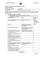
2.0 Tools
Required
List the type and size of the tools that would typically be used to disassemble the product to a
point where components and materials requiring selective treatment can be removed.
Tool Description
Tool Size (if applicable)
Torx Screw Driver
+Philips Screw Driver
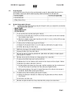
3.0 Product
Disassembly
Process
3.1
List the basic steps that should typically be followed to remove components and materials
requiring selective treatment:
- RISER CARDS
- USB+POWER CARD
- SYSTEM BOARD
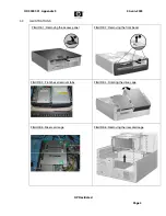
1
To remove the access panel (see Figure 1 below):
a) On the top of the computer, locate the cover latch. Pull up and hold the latch to release
the computer access panel.
b) Slide the computer access panel back about 0.5 inch (1.25 cm), and then lift the access
panel up and off the chassis.
2
To remove the front bezel (see Figure 2 & 3 below):
a) Depress the three plastic tabs on top of the bezel as indicated by the green arrows.
b) Pull the bezel away from the chassis.
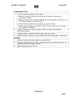
3
Rotate the drive cage to the upright position (see Figure 4 below).
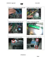
4
Unplug all cables from the system board.
5
Remove the riser card cage by grasping the green labels and pulling it straight upward
(see Figures 5 & 6 below).
6
Remove riser cards from the riser card cage using a torx screw driver.
7
To remove the USB+Power card from the AGP slot:
a) Release the slot cover retention latch located on the chassis wall (see Figure 7 below).
b) Remove any cables connected to the card.
c) Pull the retention arm away from the socket, and then carefully rock the card back and
forth until the connectors pull free from the socket (see Figure 8 below).
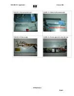
d) Lift the card straight up, then pull it in toward the center of the chassis to maneuver it
around the chassis frame (see Figure 9 below).
8
To release the system board tray (see Figure 10 below):
a) Depress the release mechanism as indicated by the green label, and then slide the
tray forward.
b) Lift the tray out of the unit.
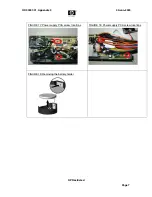
9
Remove the system board from the system board tray using a torx screw driver.